Convenient equipment overhaul inlet structure

A technology for equipment maintenance and entrance, which is applied to mechanical equipment, engine seals, engine frames, etc. It can solve the problems of laborious opening of the cover plate, large cover plate volume, and difficulty in moving, etc., to improve the sealing performance and the overall structure is simple and stable , the effect of improving convenience

Inactive Publication Date: 2020-11-27
中电诚达医药工程设计(河北)有限公司
View PDF15 Cites 1 Cited by
  • Summary
  • Abstract
  • Description
  • Claims
  • Application Information

AI Technical Summary

Problems solved by technology

[0003] At present, when maintenance personnel open the inspection port, after unscrewing the bolts on the cover plate, they need to move the cover plate to one side of the inspection port, but the cover plate is generally large in size and heavy in weight, making it difficult to move
[0004] In view of the related technologies mentioned above, the inventor believes that there is a defect that it is laborious to open the cover plate during internal maintenance of the equipment

Method used


Image

  • Convenient equipment overhaul inlet structure
  • Convenient equipment overhaul inlet structure
  • Convenient equipment overhaul inlet structure

Examples


Embodiment 1

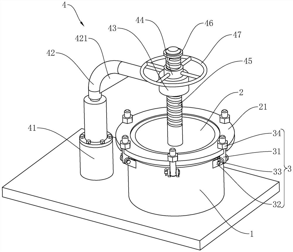
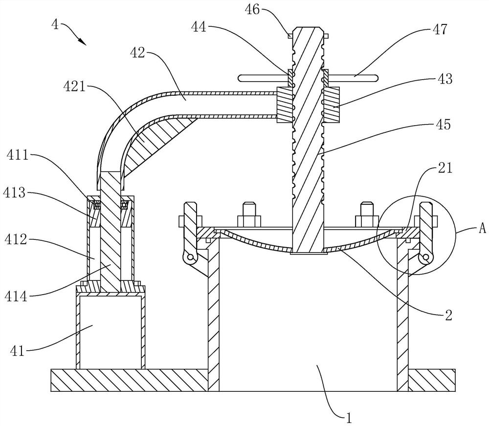
[0041] refer to figure 1 The equipment maintenance entrance structure includes a maintenance pipeline 1, a cover plate 2 arranged at the end of the maintenance pipeline 1 away from the equipment, a plurality of locking pieces 3 arranged between the cover plate 2 and the maintenance pipeline 1, and a A lifting mechanism 4 for driving the cover plate 2 to move.

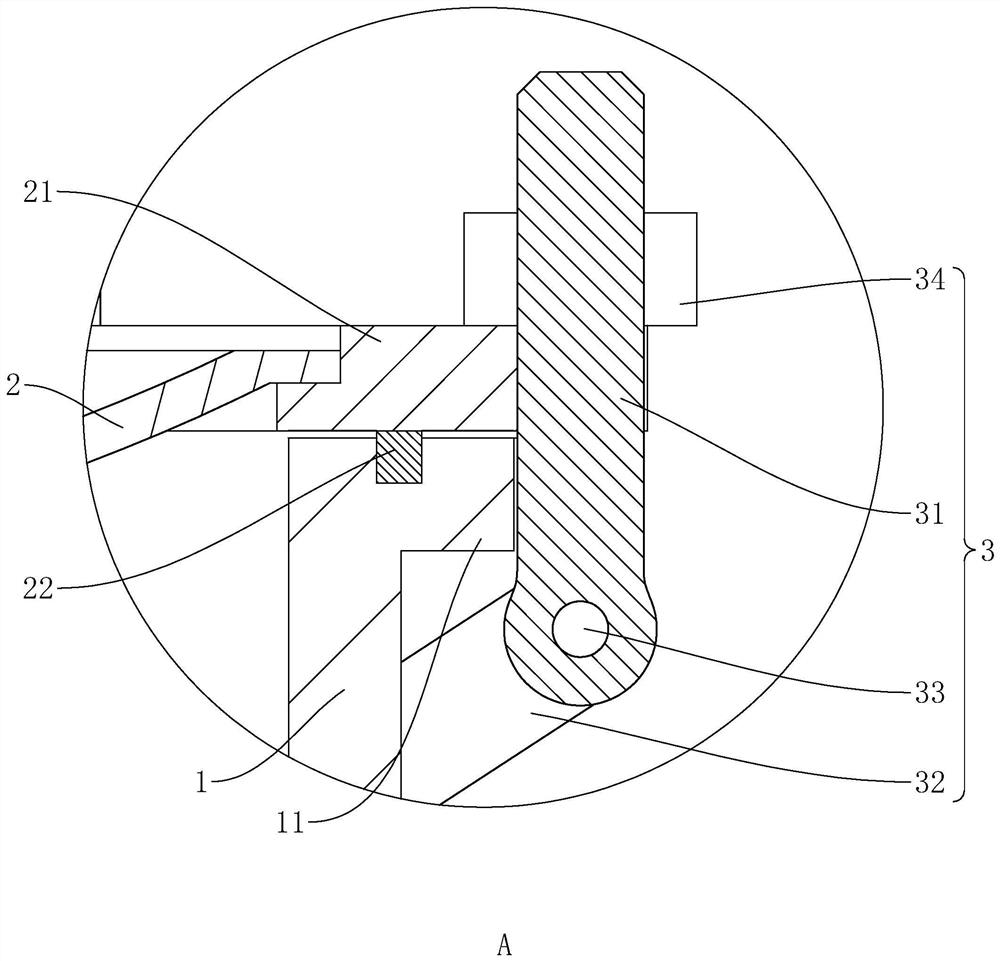
[0042] refer to figure 1 and figure 2 The maintenance pipeline 1 is arranged as a hollow circular pipeline inside, and the maintenance pipeline 1 is welded vertically on the shell or frame of the equipment, and communicates with the inside of the equipment; the cover plate 2 is set at the top opening of the maintenance pipeline 1, and the The top opening of the maintenance pipeline 1 is closed, and the flange 21 is welded on the side wall of the cover plate 2 along its circumference, that is, the flange 21 is arranged in a ring; Distributed at even intervals, a plurality of locking parts 3 cooperate with the flange ...

Embodiment 2

[0051] The difference between this embodiment and Embodiment 1 is that the main shaft 414 is provided with a limiting disk 5 .

[0052] refer to Figure 6 , the limit plate 5 is located inside the seat body 412, and the limit plate 5 is sleeved on the main shaft 414 and fixedly connected with it, the diameter of the limit plate 5 is smaller than the inner diameter of the seat body 412; the limit plate 5 is provided with a limit groove 51, Limiting groove 51 is arc-shaped setting, and the curved axis of limiting groove 51 coincides with the axis of seat body 412; The inner side walls are arranged at intervals, and the limiting block 52 slides in the limiting groove 51 . When the cover plate 2 is placed on the maintenance pipeline 1 , the limiting block 52 abuts against one end inner wall of the limiting groove 51 .

[0053] The implementation principle of Embodiment 2 is: when the main shaft 414 rotates, it will drive the limit disc 5 to rotate together. When the limit block 5...

Embodiment 3

[0055] The difference between this embodiment and Embodiment 1 is that the installation position of the hand wheel 47 is different.

[0056] refer to Figure 7 and Figure 8 , one end of the support rod 42 located above the cover plate 2 is fixed with a transmission box 48, the transmission box 48 is arranged in a hollow shell, the threaded sleeve 44 is rotatably connected to the rotary box, and the screw rod 45 is threaded in the threaded sleeve 44 ; The handwheel 47 is rotatably connected on the side wall of the transmission box 48, and the axis of the handwheel 47 is perpendicular to the axis of the threaded sleeve 44. A transmission assembly 49 is arranged between the handwheel 47 and the threaded sleeve 44, and the handwheel 47 The threaded sleeve 44 can be driven to rotate by the transmission assembly 49 .

[0057] refer to Figure 8 The transmission assembly 49 includes a worm 491 rotatably connected in the transmission box 48, and a worm wheel 492 sleeved on the thr...


PUM


Abstract

The invention relates to a convenient equipment overhaul inlet structure. The structure comprises an overhauling pipeline communicating with the interior of equipment for inspection, a cover plate arranged on the overhauling pipeline, a flange plate arranged on the cover plate and fixedly connected with the same, a plurality of locking pieces arranged between the flange disc and overhauling pipeline, and a lifting mechanism arranged on one side of the overhauling pipeline and used for lifting the cover plate from the overhauling pipeline, wherein the plurality of locking pieces lock the flangedisc on the overhauling pipeline, and the cover plate is used for closing an opening of the overhauling pipeline. The structure disclosed by the invention has the effect that maintainers can open orclose the cover plate more conveniently.

Description

technical field [0001] The present application relates to the field of inspection entrances inside equipment, in particular to a convenient structure for inspection entrances of equipment. Background technique [0002] On some larger equipment, an inspection port for people to enter and exit is usually set up on the casing or rack of the equipment, so as to facilitate the maintenance and replacement of the internal parts of the equipment, and, in order to ensure the safety of the inspection port Safety, to prevent other personnel from falling into the equipment by mistake, when the maintenance work is not performed, the inspection port will be closed with a cover plate and connected to the equipment casing or rack. [0003] At present, when maintenance personnel open the inspection port, they need to move the cover to one side of the inspection port after unscrewing the bolts on the cover. However, the cover is generally large in size and heavy in weight, making it difficult...

Claims


Application Information

Patent Timeline
Patent Type & Authority Applications(China)
IPC IPC(8): F16M1/00F16J15/02F16J15/06
CPCF16M1/00F16J15/02F16J15/061
Inventor 宋炎江王芬卿赵奎刘晓丽
Owner 中电诚达医药工程设计(河北)有限公司
Why Eureka
Try Eureka