Detector non-uniformity correction method and system

A non-uniform calibration and detector technology, applied in electrical radiation detectors, radiation pyrometry, instruments, etc., can solve the problem of difficulty in improving measurement accuracy, and achieve the effect of reducing the burden of calibration and improving calibration accuracy.

Active Publication Date: 2020-11-27
南京智谱科技有限公司
View PDF6 Cites 2 Cited by
  • Summary
  • Abstract
  • Description
  • Claims
  • Application Information

AI Technical Summary

Problems solved by technology

[0004] In summary, the correction of the non-uniformity of the detector in the prior art mainly focuses on correcting it after imaging. Therefore, the correction method of the prior art only corrects the non-uniformity after imaging, which makes it difficult to improve the measurement accuracy.

Method used


Image

  • Detector non-uniformity correction method and system
  • Detector non-uniformity correction method and system
  • Detector non-uniformity correction method and system

Examples


Embodiment Construction

[0086] In order to facilitate the understanding of the present application, the present application will be described more fully below with reference to the relevant drawings. A preferred embodiment of the application is shown in the drawings. However, the present application can be implemented in many different forms and is not limited to the embodiments described herein. On the contrary, the purpose of providing these embodiments is to make the disclosure of this application more thorough and comprehensive.

[0087] In the following description, the terms "first\second\third, etc." or module A, module B, module C, etc. are only used to distinguish similar objects, and do not represent a specific ordering of objects. It is understandable Obviously, where permitted, the specific order or sequence can be interchanged such that the embodiments of the application described herein can be practiced in other sequences than those illustrated or described herein.

[0088] In the fol...


PUM


Abstract

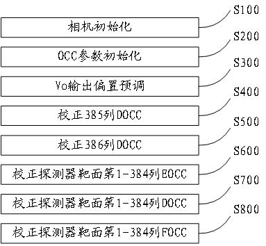
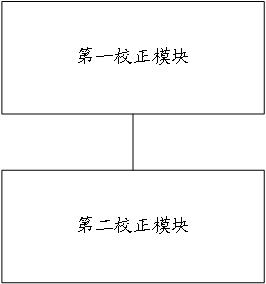
The invention relates to a detector non-uniformity correction method and system, a computing device and a storage medium. The method comprises the step of: simultaneously correcting all columns of OCCdata in OCC data of a first area in an OCC parameter list, so as to enable the mean value of pixel values outputted by all pixels of a detector array to be closest to a preset pixel target value; and / or correcting each piece of OCC data in OCC data of a second area in the OCC parameter list, so as to enable the pixel value output by each piece of OCC data at each pixel point corresponding to thedetector array to be closest to the preset pixel target value. According to the technical scheme provided by the invention, non-uniformity correction is carried out on the detector during imaging, thecorrection precision can be improved, and the correction difficulty after imaging is reduced.

Description

technical field [0001] The present application relates to the technical field of instrument calibration, in particular to a detector non-uniform calibration method and system. Background technique [0002] The detector has many advantages such as fast response, high resolution, small pixel spacing, and low cost, so the detector is very popular in the market. However, the non-uniformity of the detector is caused by the influence of the material and manufacturing process of the infrared focal plane array, which affects the measurement accuracy of the detector. [0003] At present, the method of correcting the non-uniformity of the detector is generally based on the two-point correction of the high and low temperature blackbody. This method is to project the detector to the Under the same response, in order to realize the correction of its non-uniformity. In addition, the non-uniformity correction method of the detector in the prior art also includes the shading correction ...

Claims


Application Information

Patent Timeline
Patent Type & Authority Applications(China)
IPC IPC(8): G01J5/00G01J5/10
CPCG01J5/00G01J5/10G01J2005/0077G01J5/80
Inventor 蔡李靖黄尔齐邓智威字崇德陈林森
Owner 南京智谱科技有限公司
Why Eureka
Try Eureka