
Concrete torpedo ladle on-site debugging method and debugging system and readable storage medium

A field debugging, torpedo tank technology, applied in control/adjustment system, test/monitoring control system, general control system, etc., can solve the problem of low accuracy of maximum position and minimum position value, complicated field debugging, and inability to drive chemical equipment and other problems, to achieve the effect of reducing manual adjustment operations, improving friendliness, and improving work efficiency

Active Publication Date: 2020-11-27
筑友智造智能科技有限公司
View PDF10 Cites 1 Cited by
  • Summary
  • Abstract
  • Description
  • Claims
  • Application Information

AI Technical Summary

Problems solved by technology

[0008] The object of the present invention is to provide a concrete torpedo tank on-site debugging method, a debugging system and a readable storage medium, which can realize that the torpedo tank stops moving at the maximum position and the minimum position through dual control, and solve the on-site debugging complexity that exists in the above-mentioned control method. The value accuracy of the maximum position and the minimum position is not high, and the data of the maximum position and the minimum position are reset to zero and initialized to zero, so that the device cannot be driven, etc.

Method used


Image

  • Concrete torpedo ladle on-site debugging method and debugging system and readable storage medium
  • Concrete torpedo ladle on-site debugging method and debugging system and readable storage medium
  • Concrete torpedo ladle on-site debugging method and debugging system and readable storage medium

Examples


Embodiment Construction

[0037] Preferred embodiments of the present invention are provided below to help further understanding of the present invention. Those skilled in the art should understand that the descriptions of the embodiments of the present invention are only exemplary, and are not intended to limit the solution of the present invention.

[0038] In the prefabricated component production plant, there is a concrete mixing station. The concrete at the mixing station is delivered to the distribution machine at the designated position on the production line through the torpedo tank, and the distribution machine pours concrete on the surface of the formwork according to the production cycle. The running track of the torpedo tank is fixed. In order to solve the problems such as the complexity of on-site debugging of the torpedo tank, the low accuracy of the maximum position and the minimum position, and the inability to drive the chemical equipment due to the data of the maximum position and the ...


PUM


Abstract

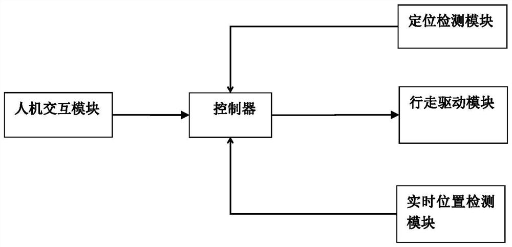
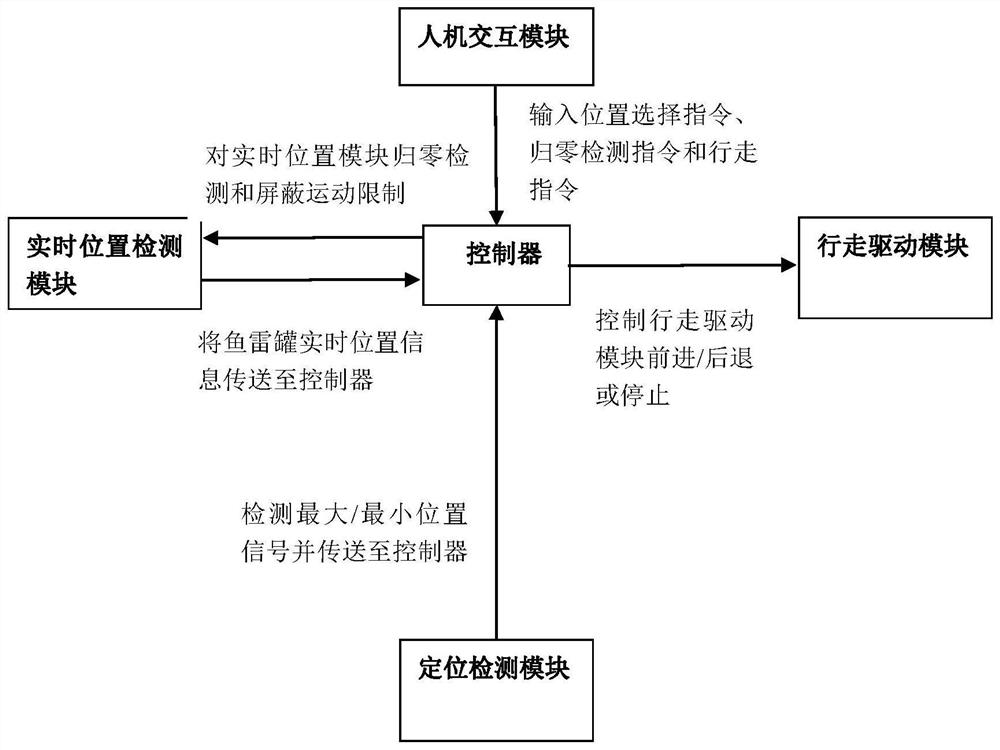
The invention relates to a torpedo ladle on-site debugging method comprising the following steps: acquiring a zeroing detection instruction, and zeroing the position data of a torpedo ladle accordingto the zeroing detection instruction; obtaining a position selection instruction and a walking instruction; controlling the torpedo ladle to operate according to the walking instruction; acquiring current position data of the torpedo ladle; and when a detection signal corresponding to the position selection instruction is received, determining that the current position data of the torpedo ladle isa position value corresponding to the position selection instruction. The invention further provides a torpedo ladle on-site debugging system. The torpedo ladle on-site debugging system comprises a walking driving module, a real-time position detection module, a positioning module and a controller. The walking driving module is used for executing a command issued by the controller; the real-timeposition detection module is used for detecting the current position of the torpedo ladle and feeding back the position to the controller; the positioning module is used for feeding back a detection signal corresponding to the position selection instruction to the controller when the torpedo ladle reaches the position corresponding to the position selection instruction; the controller includes a processor, a memory, and a computing program stored on the memory that is executable by the processor.

Description

technical field [0001] The invention belongs to the technical field of prefabricated parts production, and in particular relates to an on-site debugging method for a concrete torpedo tank, a debugging system and a readable storage medium. Background technique [0002] Concrete torpedo tanks are mainly used for concrete transfer in a fixed area, such as inside the PC factory, the concrete is transported from the mixing station to the placing machine through the torpedo tank. [0003] At present, the operation mode of the torpedo tank is an automatic control mode. When the operator selects the target position, the torpedo tank will automatically run to the target position such as the bottom of the corresponding mixing station or the distribution machine. When the torpedo tank runs automatically within a fixed range, it needs to stop at the maximum position and the minimum position to set the control conditions. Therefore, a position detection module is installed at the front a...

Claims


Application Information

Patent Timeline
IPC IPC(8): G05B23/02
CPCG05B23/0213G05B2219/24065
Inventor 杨军宏习可王珂
Owner 筑友智造智能科技有限公司
Learn More