Clamp switching device

A technology for switching devices and fixtures, which is applied in auxiliary devices, manufacturing tools, transportation and packaging, etc., and can solve the problems of large positioning structure, complex structure, and poor flexibility

Active Publication Date: 2020-12-01
CHERY AUTOMOBILE CO LTD
View PDF8 Cites 5 Cited by
  • Summary
  • Abstract
  • Description
  • Claims
  • Application Information

AI Technical Summary

Problems solved by technology

The main structural form is realized through the expansion and contraction of the double guide rod cylinder, or the fixture structure is fixed on the two slide rails, and the switching is realized by sliding, and the flexibility is poor; at the same time, the above two solutions can only be applied to two types of vehicles. The speed of model replacement has limitations; secondly, the positioning accuracy is insufficient, and an additional limit structure is required, resulting in an oversized and complex structure of the overall positioning structure, which affects welding operations

Method used


Image

  • Clamp switching device
  • Clamp switching device
  • Clamp switching device

Examples


Embodiment Construction

[0016] Combine below Figure 1-Figure 11 The present invention is discussed in further detail.

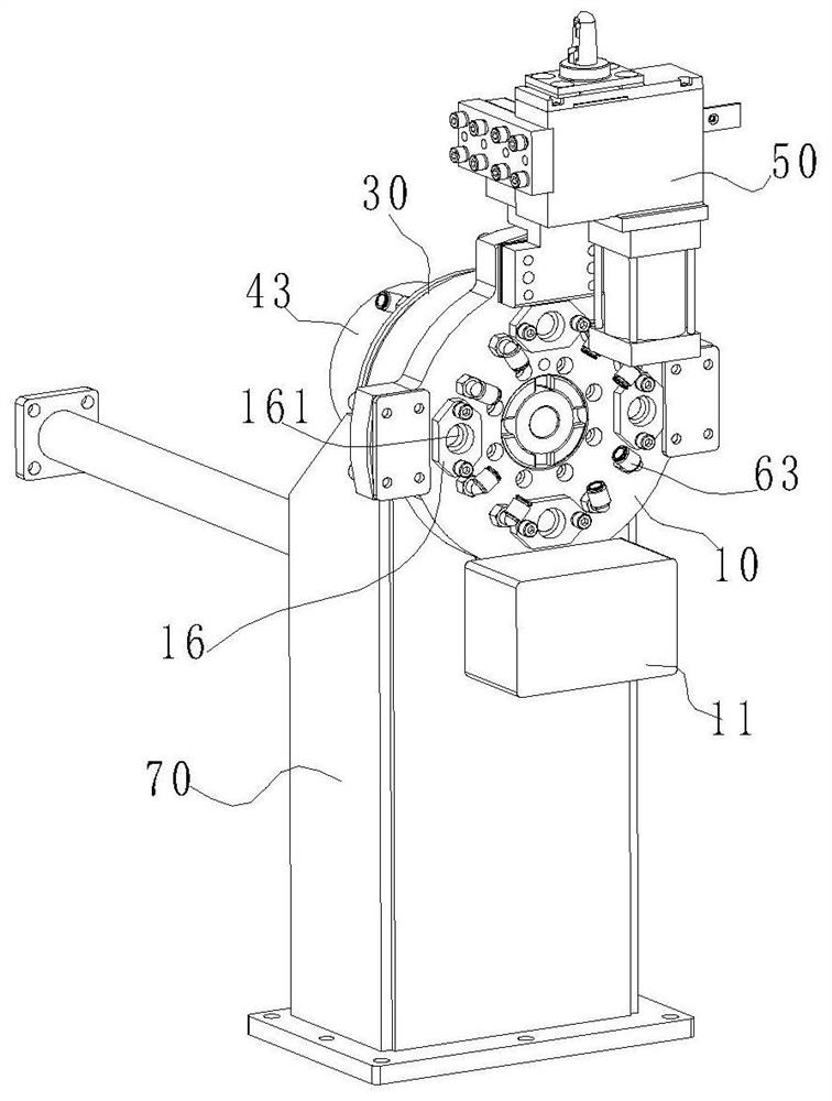
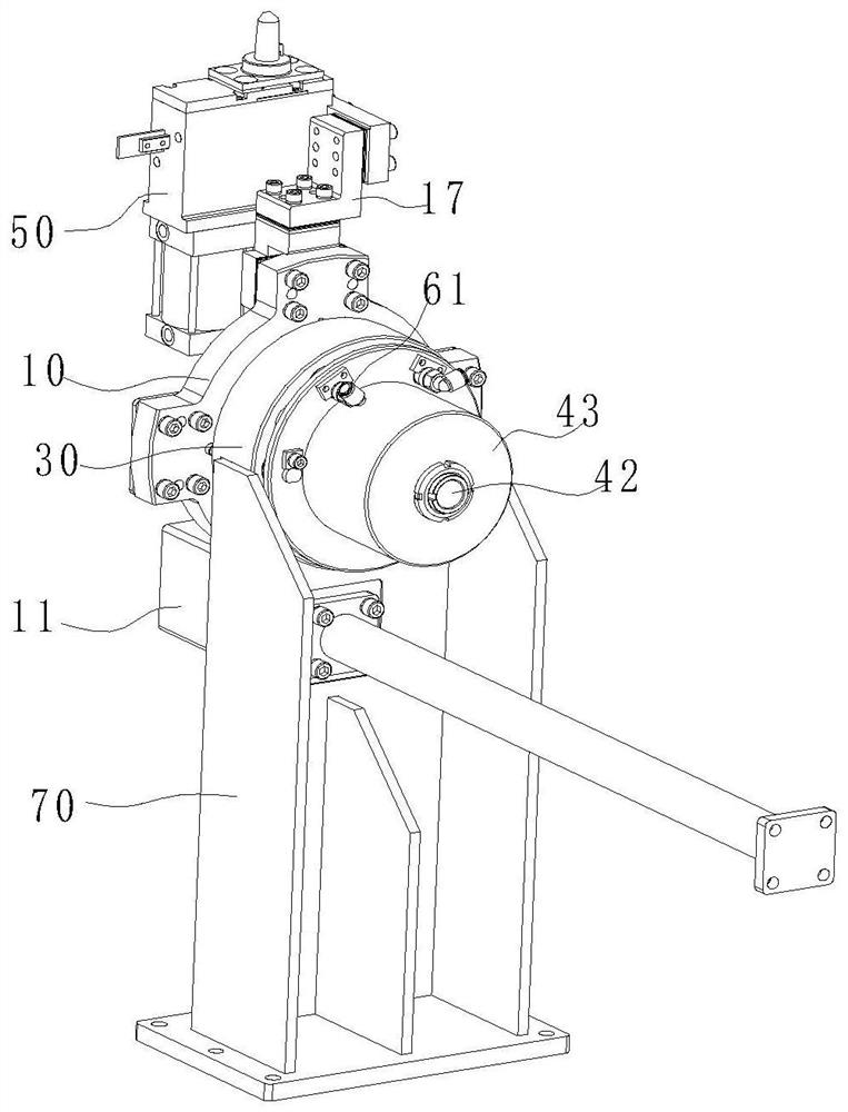
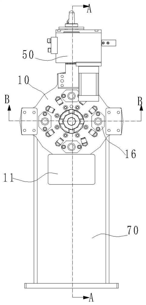
[0017] A clamp switching device, comprising a mounting plate 10, the clamping mechanism 50 for clamping the vehicle body is arranged at intervals on the peripheral surface of the mounting plate 10, the mounting plate 10 is coaxially fixed with a rotating shaft 21, and the rotating shaft 21 is rotated and arranged on a fixed On the seat 30 , a positioning pin 41 is also arranged on the fixed seat 30 , and when the positioning pin 41 slides along its own axial direction, it is inserted into and locked with the positioning hole 12 provided on the mounting plate 10 or separated and unlocked. The axial direction of the locating pin 41 and the axial direction of the rotating shaft 21 may be parallel or non-parallel, as long as the locking and unlocking of the mounting disk 10 can be realized, the axial direction of the locating pin 41 is preferably parallel to the rotating shaft 21. Dur...


PUM


Abstract

The invention aims to provide a clamp switching device which can achieve the collinear production of multiple vehicle types and enhance the flexibility of a welding main line. A clamping mechanism used for clamping a vehicle body is arranged on the circumferential surface of an installation disc in a separated mode, the installation disc and a rotating shaft are coaxially fixed, and the rotating shaft is rotationally arranged on a fixing base. Locating pins are further arranged on the fixing base, and the locating pins are inserted into locating holes formed in the installation disc to be locked or are separated from the locating holes to be unlocked when sliding in the axial directions of the locating pins. When the device is normally used, the locating pins are inserted into the locatingholes to limit the rotation of the installation disc, the clamping mechanism clamps vehicle body, when the vehicle type needs to be switched, the external force is inserted into the locating holes topush the locating pins out of the locating holes to be separated, the constraint of the locating pins on the installation disc is relieved at this moment, then the rotation is conducted through the external force, the external force is withdrawn after the installation disc rotates to the position of the clamping mechanism corresponding to the switched vehicle type along with the device, the locating pins are inserted into the locating holes again to lock the installation disc again, and therefore the switching usage of different vehicle types is achieved.

Description

technical field [0001] The invention relates to the technical field of automobile automatic production lines, and specifically designs a fixture switching device. Background technique [0002] During the planning process of the welding production line of the automobile OEM, the requirements for the flexible production capacity of the production line are getting higher and higher, and improving the commonality of the main line fixtures of the welding production line is the key to ensuring the flexible production of multiple models in the welding production line. If you want to realize the flexible mixed line production of multiple models, you need to ensure the automatic switching of different welding fixtures to meet the needs of collinear production of different models. However, the fixture design of the welding production line of each car factory basically adopts a fixed method, that is, the fixture is distributed on the welding line, and each clamping point is fixed, and ...

Claims


Application Information

Patent Timeline
Patent Type & Authority Applications(China)
IPC IPC(8): B23K37/04
CPCB23K37/0443B23K2101/006
Inventor 郭峰张浩
Owner CHERY AUTOMOBILE CO LTD
Why Eureka
Try Eureka