Eureka AIR delivers breakthrough ideas for toughest innovation challenges, trusted by R&D personnel around the world.

Tool jig for assembling surgical robot instrument connecting mechanism

A surgical robot and connecting mechanism technology, applied in the direction of surgical instrument support, surgical robot, hand-held tools, etc., can solve the problems of laborious and troublesome installation, and achieve the effect of easy assembly

Active Publication Date: 2020-12-01
周长学
View PDF9 Cites 0 Cited by
  • Summary
  • Abstract
  • Description
  • Claims
  • Application Information

AI Technical Summary

Problems solved by technology

[0002] During laparoscopic surgery, it is necessary to find a suitable connection mechanism between the laparoscopic surgical robot instrument and the instrument base to form a docking between the laparoscopic surgical robot instrument and the instrument base. The patent No. 201611257011.3 proposes a It is used for the connection mechanism of robotic instruments in laparoscopic surgery; the mechanism is composed of the lower cover of micro-instruments, the upper cover of micro-instruments, springs and limit screws, the lower cover of micro-instruments is rectangular, the upper cover of micro-instruments is circular, and the lower cover of micro-instruments Placed in the upper cover of the micro-device; the spring is arranged between the upper cover of the micro-device and the lower cover of the micro-device, and the limit screw is used to limit the upper cover of the micro-device and the lower cover of the micro-device; when this part is installed, use Manual assembly. During manual assembly, it is necessary to press the lower cover of the micro-device into the upper cover of the micro-device, and then install the limit screw. This manual installation is laborious and troublesome; it is necessary to design related fixtures to assist in the installation, so as to facilitate the connection mechanism of the device assembly

Method used


Image

  • Tool jig for assembling surgical robot instrument connecting mechanism
  • Tool jig for assembling surgical robot instrument connecting mechanism
  • Tool jig for assembling surgical robot instrument connecting mechanism

Examples


Embodiment

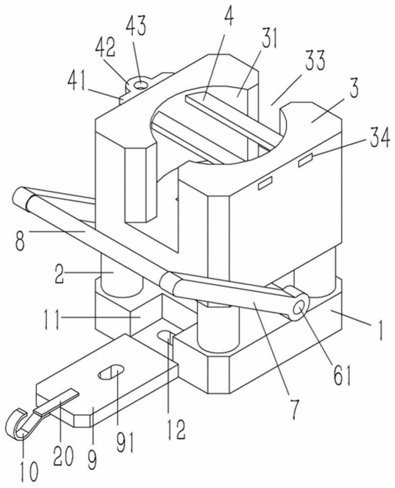
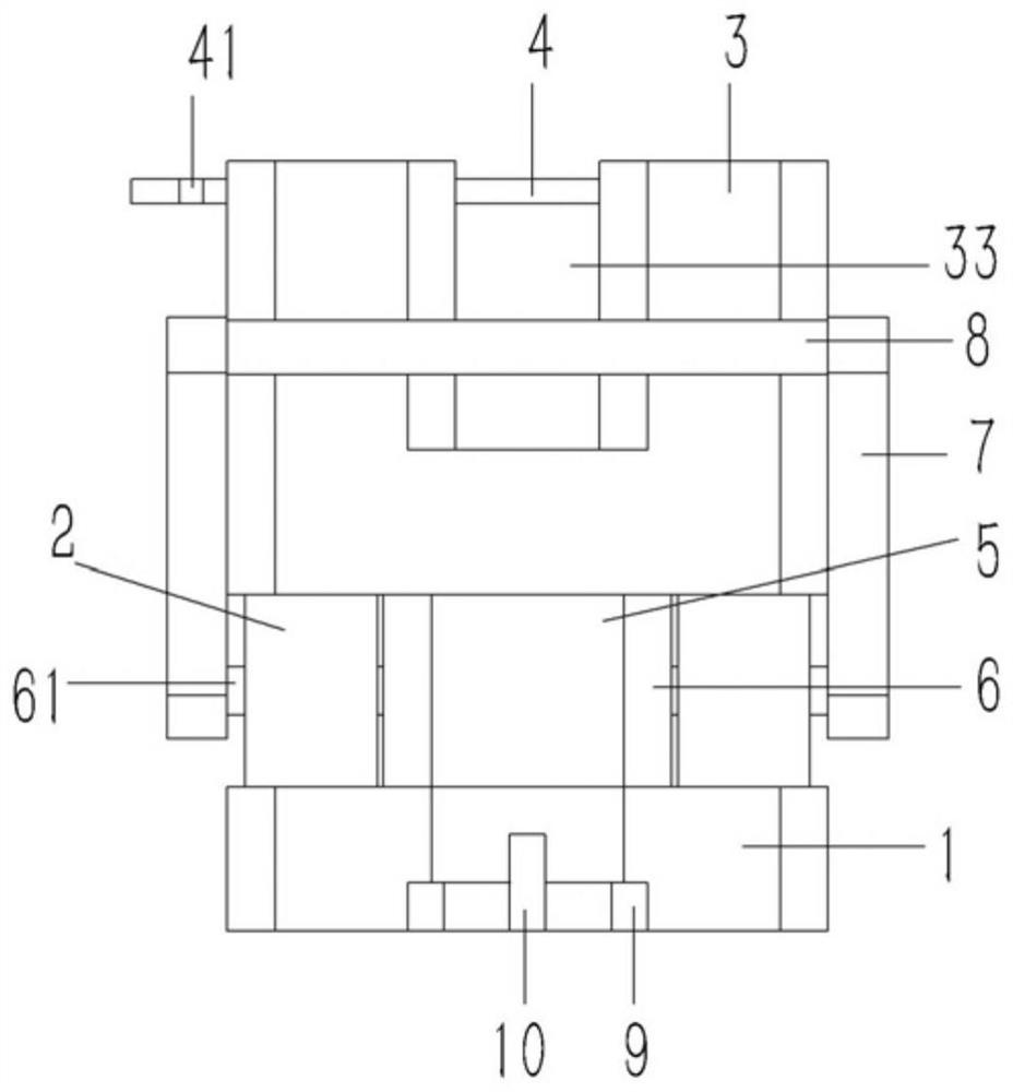
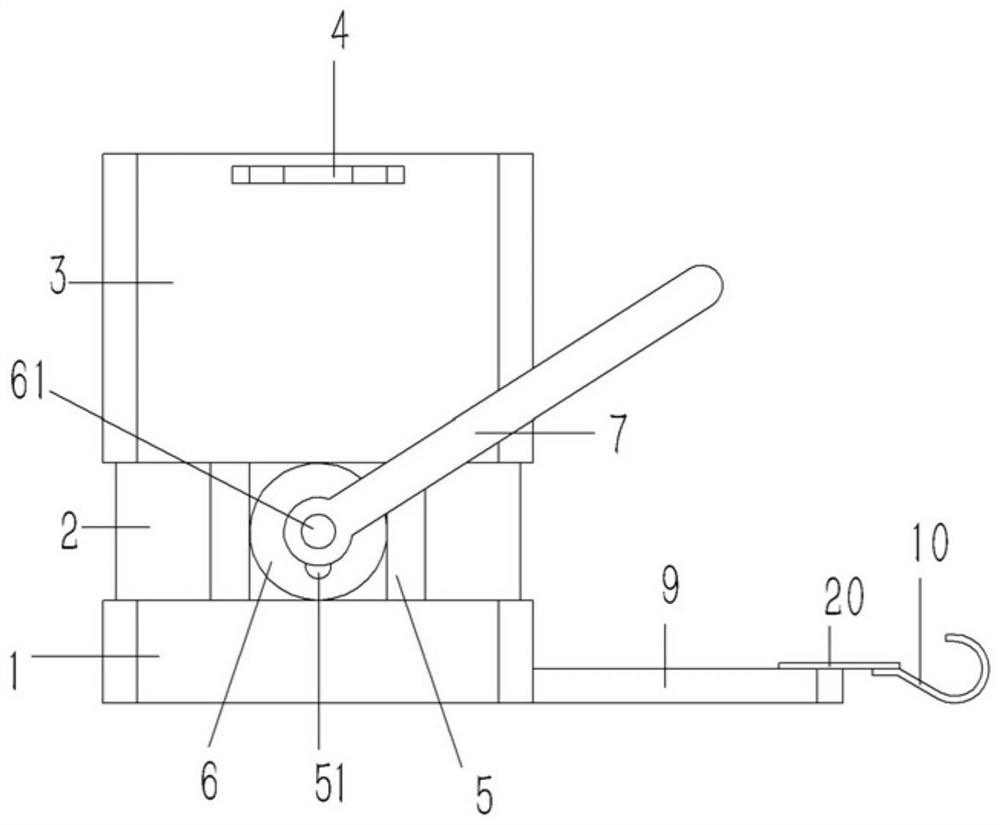
[0019] Example: see Figures 1 to 4 As shown, a tooling fixture for assembling the connection mechanism of surgical robot instruments includes a rectangular base 1, the four corners of the base 1 are fixed with columns 2, the upper end of the column 2 is fixed with a rectangular assembly base 3, and the upper end of the assembly base 3 A circular counterbore 31 is formed on the end surface, and a positioning hole 32 penetrating through the lower end surface of the assembly base 3 is formed on the bottom surface of the counterbore 31; The observation slot 33 on the front and rear end faces, the opposite inner walls on the left and right sides of the upper end of the counterbore 31 are formed with jacks 34 that run through the left and right end faces of the assembly base 3, and the jacks 34 of the assembly base 3 are plugged with Several retaining bars 4; the positioning hole 32 of the assembly base 3 is inserted with a vertical ejector block 5, the lower end of the ejector blo...


PUM


Abstract

The invention discloses a tool jig for assembling a surgical robot instrument connecting mechanism. The tool jig comprises a rectangular base, a stand column and an assembling base, a circular counterbore is formed in the upper end face of the assembling base, and a positioning hole penetrating through the lower end face of the assembling base is formed in the bottom face of the counter bore; inserting holes penetrating through the left end face and the right end face of the assembling base are formed in the opposite inner walls of the left side and the right side of the upper end of the counter bore, and a plurality of blocking strips are inserted into the inserting holes of the assembling base; a vertical material ejecting block is inserted into the positioning hole of the assembling base; and the lower end of the ejecting block is inserted into the base; driving wheels abut against the positions, between the base and the assembling base, of the left side wall and the right side wall of the ejecting block, supporting columns are formed on the left side wall and the right side wall, close to the outer edges of the lower ends of the driving wheels, of the ejecting block and inserted into the driving wheels, supporting shafts are formed in the circle centers of the driving wheels, and the outer ends of the supporting shafts extend out of the side walls of the assembling base tobe fixedly sleeved with inclined connecting rods.

Description

technical field [0001] The invention relates to the technical field of medical equipment, and more specifically relates to a tooling fixture for assembling a connecting mechanism of an instrument of a surgical robot. Background technique [0002] During laparoscopic surgery, it is necessary to find a suitable connection mechanism between the laparoscopic surgical robot instrument and the instrument base to form a docking between the laparoscopic surgical robot instrument and the instrument base. The patent No. 201611257011.3 proposes a It is used for the connection mechanism of robotic instruments in laparoscopic surgery; the mechanism is composed of the lower cover of micro-instruments, the upper cover of micro-instruments, springs and limit screws, the lower cover of micro-instruments is rectangular, the upper cover of micro-instruments is circular, and the lower cover of micro-instruments Placed in the upper cover of the micro-device; the spring is arranged between the up...

Claims


Application Information

Patent Timeline
IPC IPC(8): B25B27/00B25B27/02A61B34/30A61B90/50
CPCA61B34/30A61B90/50B25B27/00B25B27/02
Inventor 胡惠娟
Owner 周长学
Why Eureka
Eureka Blog
Learn More