
Bionic flapping wing micro aircraft with adjustable flapping angle average position and flight control method of bionic flapping wing micro aircraft

A micro-aircraft, average position technology, applied in vehicle position/route/altitude control, aircraft, non-electric variable control and other directions, can solve the increase or decrease of rough angle of attack, difficult to achieve, and is not conducive to control rudder effect evaluation and precise control design to achieve the effect of reducing complexity and improving system reliability

Active Publication Date: 2020-12-01
BEIHANG UNIV
View PDF12 Cites 2 Cited by
  • Summary
  • Abstract
  • Description
  • Claims
  • Application Information

AI Technical Summary

Problems solved by technology

This type of scheme can only roughly increase or decrease the angle of attack, and it is difficult to realize the change of the angle of attack accurately and in real time, which is not conducive to the evaluation of control rudder efficiency and precise control design
In addition, the scheme of changing the average position of the flapping angle needs to adjust and control the wing flapping motion mechanism. On the one hand, it is more difficult to realize this scheme under the requirements of miniaturization and integration design; The change is extremely sensitive, and the adjustment of the flapping motion mechanism will also cause aerodynamic changes at the same time. This solution is difficult to ensure high lift while adjusting the average position of the flapping angle.

Method used


Image

  • Bionic flapping wing micro aircraft with adjustable flapping angle average position and flight control method of bionic flapping wing micro aircraft
  • Bionic flapping wing micro aircraft with adjustable flapping angle average position and flight control method of bionic flapping wing micro aircraft
  • Bionic flapping wing micro aircraft with adjustable flapping angle average position and flight control method of bionic flapping wing micro aircraft

Examples


Embodiment Construction

[0043] The specific implementation method of the present invention will be described in detail below in conjunction with the accompanying drawings.

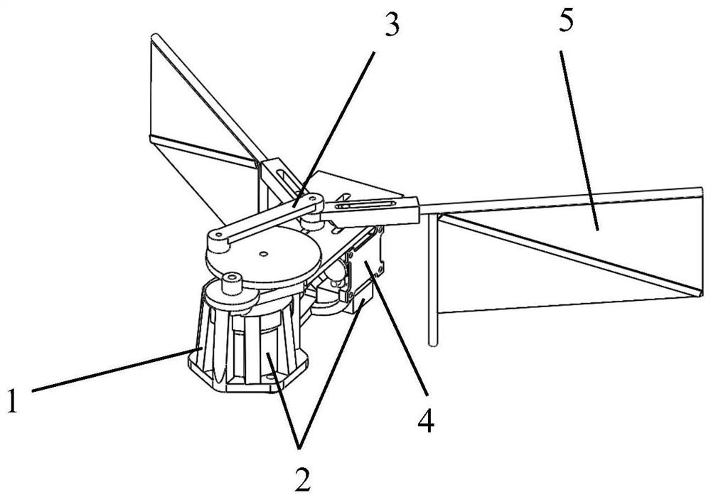
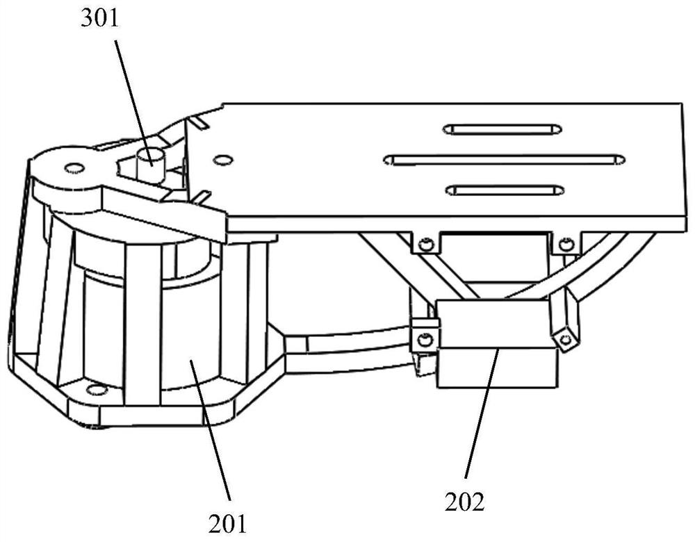
[0044] A bionic flapping-wing micro-aircraft with adjustable flapping angle and average position of the present invention comprises a base 1 , a power device 2 , a transmission mechanism 3 , a control mechanism 4 and a flapping wing 5 .

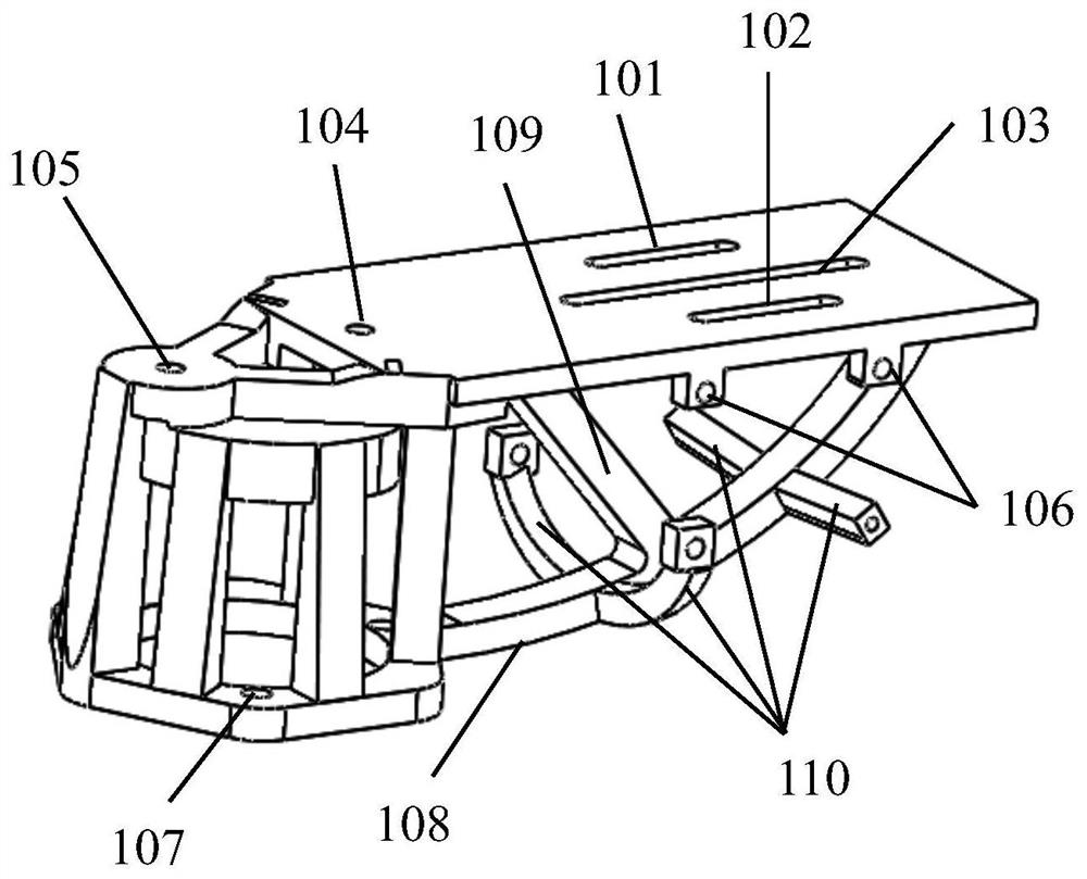
[0045] The base 1 is a three-dimensional structure, integrally formed by 3D printing, and functionally divided into a plane installation area, a power device installation area and a supporting frame. The main body of the planar installation area is a flat structure, including a left chute 101 , a right chute 102 , a middle chute 103 , a single-layer gear mounting hole 104 , a double-layer gear mounting hole 105 , and a steering gear mounting hole 106 . The power device installation area is a cavity formed by seven inclined columns and a circular platform, and the power device 2 is placed in the ...


PUM


Abstract

The invention discloses a bionic flapping wing micro aircraft with an adjustable flapping angle average position and a flight control method of the bionic flapping wing micro aircraft. The device comprises a base, a power device, a transmission mechanism, a control mechanism and flapping wings. The power device, the transmission mechanism and the control mechanism are fixed to the base, and vibration of the base is reduced through a reinforcing beam. The transmission mechanism comprises a gear reduction set and a connecting rod mechanism, the connecting rod is connected with the gear, the leftrocker arm and the right rocker arm to form a slider-crank mechanism, a sliding groove is formed between the left rocker arm and the right rocker arm and connected with a base sliding groove and a linear stepping steering engine output arm through rivets, and reciprocating flapping can be achieved around the connecting rivets. The control mechanism drives the connecting rivet through the output arm to achieve adjustment of the average position of the flapping angle. By means of the simple connecting rod set, bionic flapping motion is achieved, the complexity of the mechanism is reduced, and machining is facilitated; meanwhile, by adjusting the average position of the flapping angle, the generation of the control moment is decoupled from the lift force of the aircraft, and maneuvering suchas pitching and circling can be realized.

Description

technical field [0001] The invention relates to the field of micro-aircraft, in particular to a bionic flapping-wing micro-aircraft with adjustable flap angle and average position and a flight control method thereof. Background technique [0002] The rapid development of micro-electromechanical technology has made it possible to miniaturize traditional aircraft. In this context, the concept of micro air vehicle was proposed in the 1990s. This type of aircraft has a wide range of military and civilian uses, and has become a research hotspot in this field. [0003] According to the principle of lift generation, MAVs can be roughly divided into fixed-wing MAVs, rotary-wing MAVs, and bionic flapping-wing MAVs. Compared with traditional aircraft, MAVs are small in size and low in flight speed, so their flying Reynolds number is also small during operation, and the aircraft faces strong viscous effects during flight. Efficiency is generally low. Insects and hummingbirds are nat...

Claims


Application Information

Patent Timeline
IPC IPC(8): B64C33/02B64D27/24G05D1/08
CPCB64C33/02B64D27/24G05D1/0808
Inventor 吴江浩程诚
Owner BEIHANG UNIV
Learn More