Disinfection equipment for disinfection supply room

A technology for disinfection equipment and supply rooms, which is applied in the direction of sanitary equipment for toilets, disinfection, and water supply equipment, etc. It can solve the problems of reducing the performance of the device, affecting the effect of disinfection, and difficult equipment cleaning, so as to increase stability and improve disinfection. effect, reducing the effect of collision

Inactive Publication Date: 2020-12-04
日照市岚山区人民医院
View PDF1 Cites 1 Cited by
  • Summary
  • Abstract
  • Description
  • Claims
  • Application Information

AI Technical Summary

Problems solved by technology

[0004] When the disinfection equipment in the above-mentioned patent is in use, it is difficult to clean the surface of the equipment, thereby affecting the disinfection effect and reducing the performance of the device

Method used


Image

  • Disinfection equipment for disinfection supply room
  • Disinfection equipment for disinfection supply room
  • Disinfection equipment for disinfection supply room

Examples


Embodiment 1

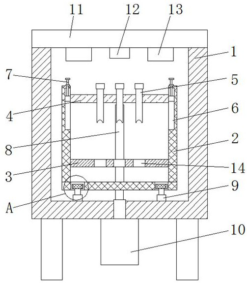
[0031] see Figure 1 to Figure 6 , the present invention provides a technical solution for disinfection equipment for disinfection supply rooms: a disinfection equipment for disinfection supply rooms, including a device main body 1, a placement frame 2 is arranged inside the device body 1, and the interior of the placement frame 2 is close to the lower end A partition 3 is installed at a fixed position, and a cover plate 4 is provided on the inside of the shelf 2 near the upper end, and the cover plate 4 is located directly above the partition 3, and movable slots are opened on the inside of the main body 1 near both sides. 15. A rotating rod 16 is installed inside the movable groove 15, and one end of the rotating rod 16 is fixedly connected with a motor 17. The outer surface of the rotating rod 16 is threaded with a moving plate 18, and the moving plate 18 is slidably installed inside the movable groove 15. A brush 19 is provided at a position corresponding to the moving pla...

Embodiment 2

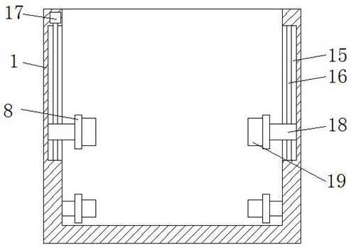
[0036] Such as Figure 5 with Image 6 As shown, in the case that other parts are the same as in Embodiment 1, the difference between this embodiment and Embodiment 1 is that: the inner surface of the placement frame 2 is provided with a chute 6 near the front and rear ends, and the inside of the chute 6 slides Side plates 24 are installed, and the two side plates 24 are fixedly installed on the two end faces of the cover plate 4 respectively, and the upper end faces of the side plates 24 are fixedly equipped with the adjusting rod 7, and the outer surface of the adjusting rod 7 is screwed with the rotating plate 20 , the lower end surface of the rotating plate 20 is fixedly equipped with a sleeve 25, the sleeve 25 is threadedly mounted on the inside of the placement frame 2 near the upper end, and the sleeve 25 is threaded with the adjusting rod 7, and the upper end of the adjusting rod 7 extends to The outside of the placement frame 2 is fixedly installed with an operation ...

Embodiment 3

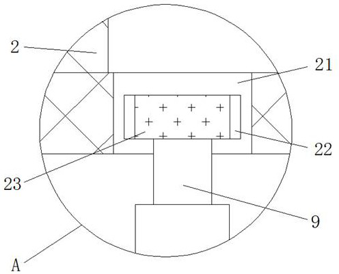
[0041] Such as figure 1 with image 3 As shown, in the case that other parts are all the same as in Embodiment 1, the difference between this embodiment and Embodiment 1 is that a fixed plate 21 is fixedly installed on the lower end surface of the placement frame 2 near the outside, and the lower end surface of the fixed plate 21 An annular groove 22 is opened, and a limiting plate 23 is installed in rotation inside the annular groove 22 , and an electric push rod 9 is fixedly connected between the lower end surface of the limiting plate 23 and the equipment main body 1 .

[0042] The middle position of the outer surface of the lower end of the placement frame 2 is fixedly connected with a motor 10 through a telescopic rod, and two electric push rods 9 are symmetrical about the motor 10 .

[0043] Working principle: the motor 10 drives the placement frame 2 to rotate, and the rotation of the placement frame 2 prompts the limit plate 23 to rotate inside the annular groove 22 t...


PUM


Abstract

The invention discloses disinfection equipment for a disinfection supply room, and belongs to the technical field of disinfection equipment. The disinfection equipment comprises an equipment main body, a placement rack is arranged in the equipment main body, a partition plate is fixedly installed at the position, close to the lower end, in the placement rack, a cover plate is arranged at the position, close to the upper end, in the placement rack and located over the partition plate, movable grooves are formed in the positions, close to the two sides, in the equipment main body, rotating rodsare rotationally installed in the movable grooves, one ends of the rotating rods are fixedly connected with motors, the outer side faces of the rotating rods are sleeved with movable plates in a threaded mode, the movable plates are installed in the movable grooves in a sliding mode, brushes are arranged at the positions, corresponding to the movable plates, in the placement rack, and installing plates are fixedly installed on the opposite inner side surfaces of the two movable plates. The surface of an instrument can be cleaned while being disinfected, so that the operation of a user is facilitated, the disinfection effect is improved, and the use performance of the equipment is improved.

Description

technical field [0001] The invention relates to the technical field of disinfection equipment, in particular to a disinfection equipment for a disinfection supply room. Background technique [0002] The disinfection supply room is an important department for the hospital to supply various sterile instruments, dressings and supplies. The quality of its work directly affects the quality of medical care and the safety of patients. The new construction, expansion and reconstruction of the disinfection room should improve work efficiency and ensure work quality. as a premise. The supply room should be close to the clinical departments and can be located between the inpatient department and the outpatient department. The surrounding environment should be clean and free from pollution sources, and a relatively independent area should be formed to facilitate the organization of internal work lines and avoid interference from outsiders. [0003] The existing Chinese patent (publica...

Claims


Application Information

Patent Timeline
Patent Type & Authority Applications(China)
IPC IPC(8): A61L2/18A61L2/26
CPCA61L2/18A61L2/26A61L2202/23
Inventor 刘秋芬李志艳胡淑丽
Owner 日照市岚山区人民医院
Why Eureka
Try Eureka