Sand setting device for sewage treatment
A technology for sewage treatment and sand settling, which is applied to the feeding/discharging device of the settling tank, settling tank, sedimentation separation, etc. Feed speed and smoothness, avoid clogging effect
- Summary
- Abstract
- Description
- Claims
- Application Information
AI Technical Summary
Problems solved by technology
Method used
Image
Examples
Embodiment 1
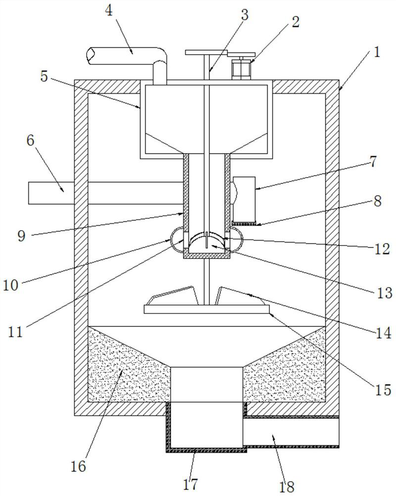
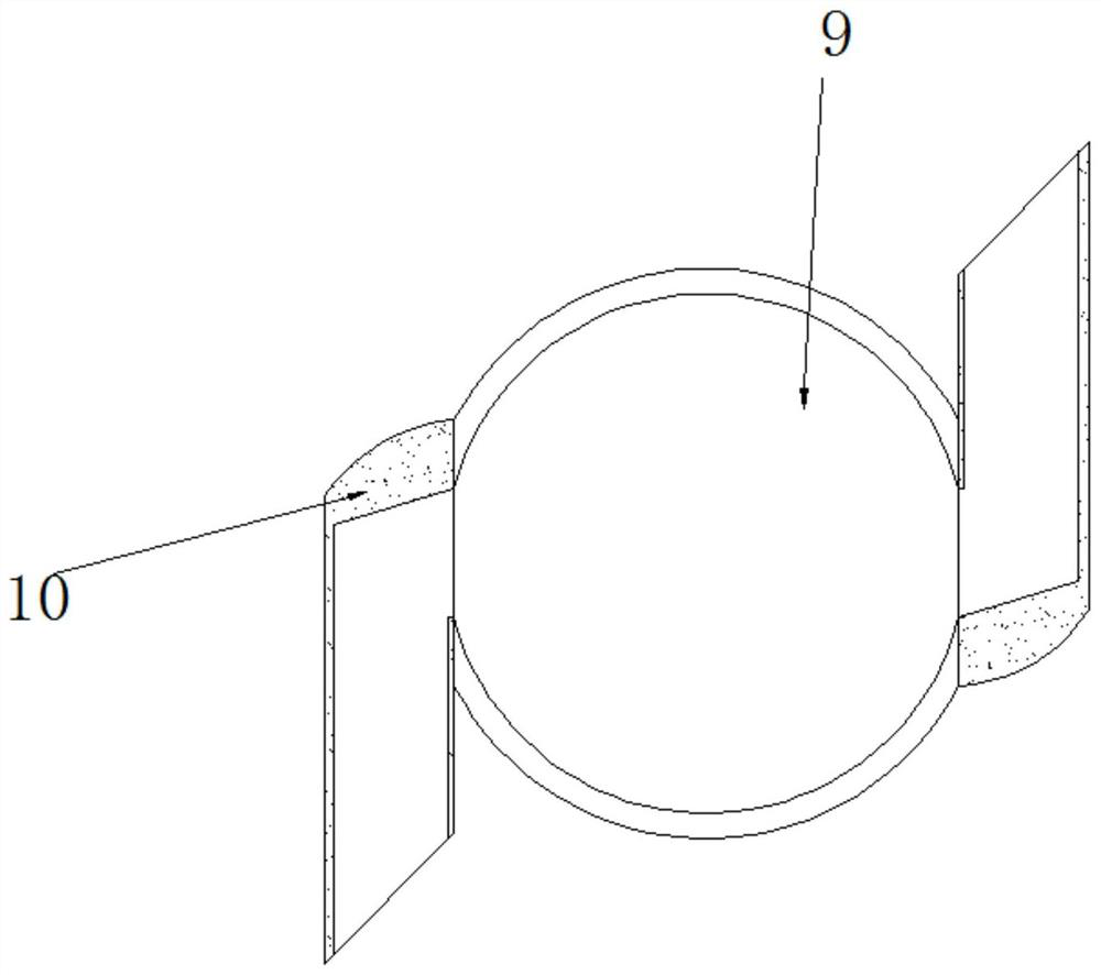
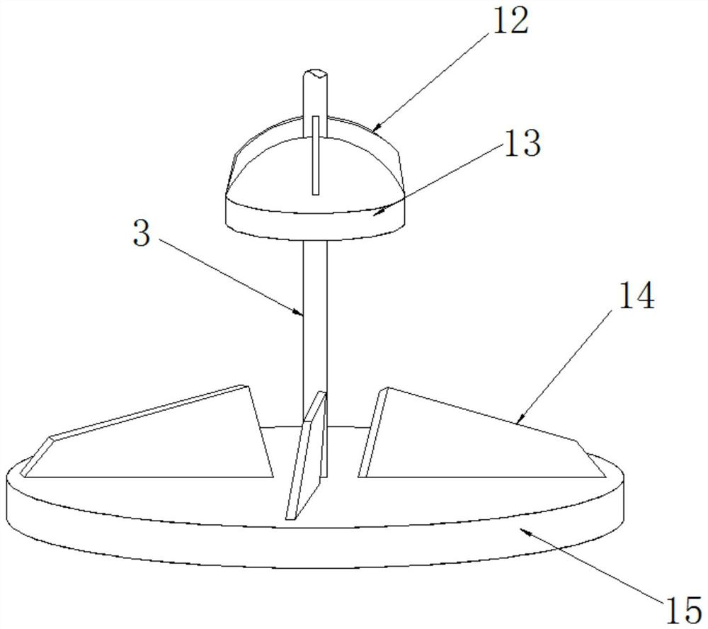
[0026] refer to Figure 1-3 , a sand settling device for sewage treatment, comprising a box body 1, an installation opening is opened at the center of the top outer wall of the box body 1, a buffer box 5 is fixed in the installation opening, and a feed pipe 4 is fixedly inserted into the top outer wall of the buffer box 5 , the center position of the outer wall at the bottom of the buffer box 5 is fixedly plugged with a buffer tube 9, and the buffer tube 9 has a guide port 11 on both sides of the bottom end of the outer wall of the circumference, and the two guide ports 11 are fixedly connected with guides in the opposite direction of the discharge port. The bottom of tube 10 and buffer tube 9 is rotated and plugged with rotating shaft 3, and the top of rotating shaft 3 passes through the top outer wall of buffer box 5 and is connected with driving mechanism 2. There is a drainage mechanism, and the bottom of the box body 1 is fixedly plugged with a discharge mechanism.
[00...
Embodiment 2
[0030] refer to Figure 4 , a sand settling device for sewage treatment, comprising a box body 1, an installation opening is opened at the center of the top outer wall of the box body 1, a buffer box 5 is fixed in the installation opening, and a feed pipe 4 is fixedly inserted into the top outer wall of the buffer box 5 , the center position of the outer wall at the bottom of the buffer box 5 is fixedly plugged with a buffer tube 9, and the buffer tube 9 has a guide port 11 on both sides of the bottom end of the outer wall of the circumference, and the two guide ports 11 are fixedly connected with guides in the opposite direction of the discharge port. The bottom of tube 10 and buffer tube 9 is rotated and plugged with rotating shaft 3, and the top of rotating shaft 3 passes through the top outer wall of buffer box 5 and is connected with driving mechanism 2. There is a drainage mechanism, and the bottom of the box body 1 is fixedly plugged with a discharge mechanism.
[0031...
PUM
 Abstract
Description
Claims
Application Information
 - R&D Engineer
- R&D Manager
- IP Professional
- Industry Leading Data Capabilities
- Powerful AI technology
- Patent DNA Extraction
Browse by: Latest US Patents, China's latest patents, Technical Efficacy Thesaurus, Application Domain, Technology Topic, Popular Technical Reports.
© 2024 PatSnap. All rights reserved.Legal|Privacy policy|Modern Slavery Act Transparency Statement|Sitemap|About US| Contact US: help@patsnap.com


