A welding tool for antenna vibrator processing

A welding tool and antenna vibrator technology, applied in welding equipment, metal processing equipment, auxiliary welding equipment, etc., can solve the problems of welding position deviation, poor signal, unstable fixing method, etc., to avoid shaking, avoiding spark burns, Precise welding position

Active Publication Date: 2022-05-27
SHENZHEN FRD SCI & TECH
View PDF6 Cites 0 Cited by
  • Summary
  • Abstract
  • Description
  • Claims
  • Application Information

AI Technical Summary

Problems solved by technology

[0003] At present, most of the antenna vibrators on the market are assembled, some are clamped or screwed on the main rod through the rod, this fixing method is unstable, and some are fixed by welding, but they are all fixed by welding. If the side pole is manually held in contact with the main pole and then welded, the welding position will be deviated, resulting in poor signal. Therefore, a welding tool for antenna oscillator processing is proposed to solve the above problems.

Method used


Image

  • A welding tool for antenna vibrator processing
  • A welding tool for antenna vibrator processing
  • A welding tool for antenna vibrator processing

Examples


Embodiment 1

[0025] see figure 1 , figure 2 , image 3 , Figure 4 and Figure 5 , the present invention provides a kind of technical scheme:

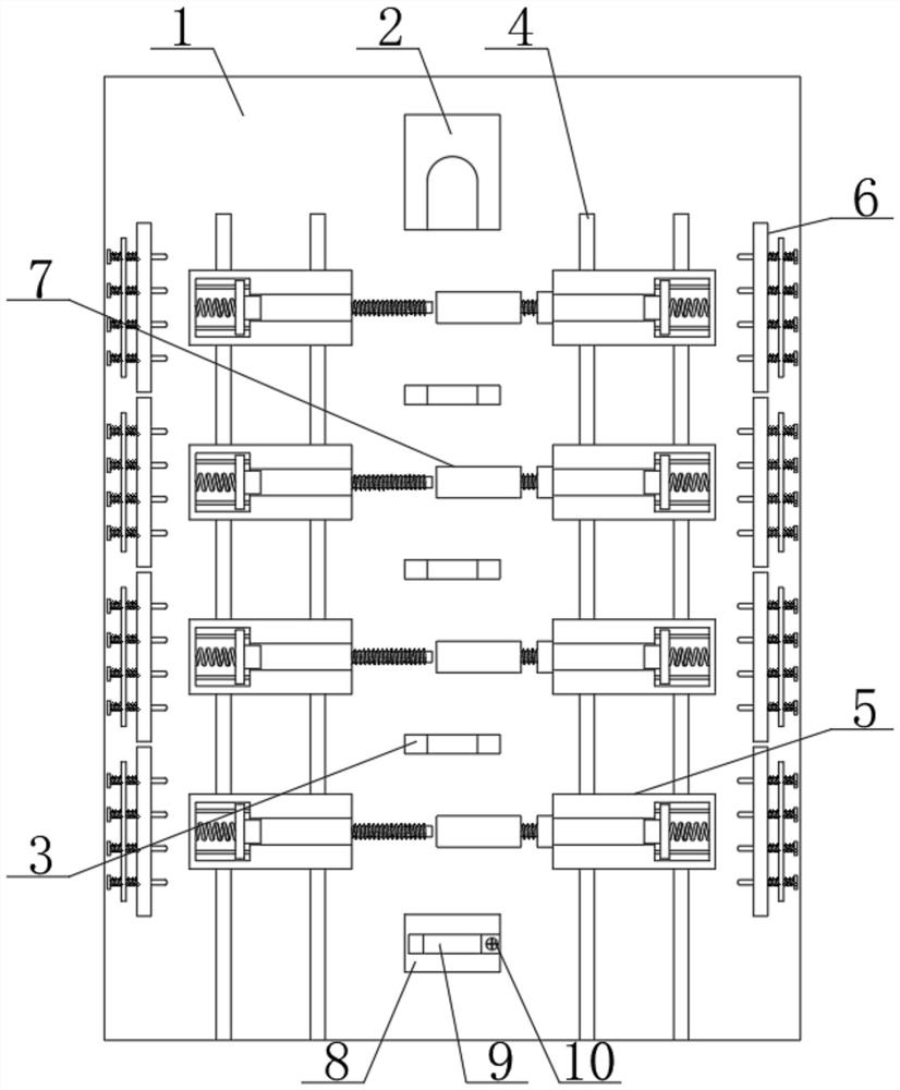
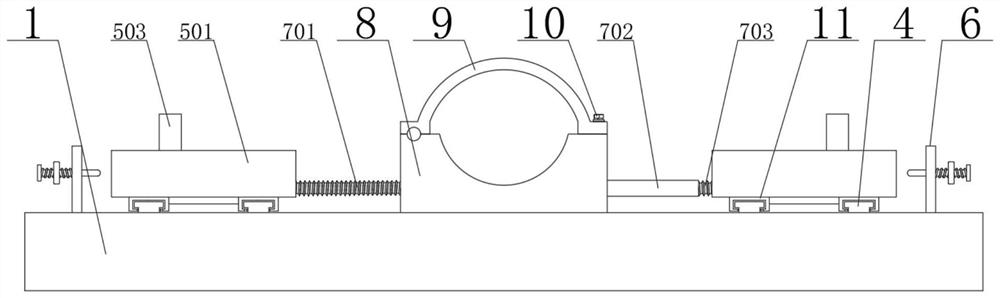
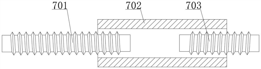
[0026] A welding tool for antenna vibrator processing, comprising a base plate 1 and an upper unit fixing block 2, an upper unit fixing block 2 is fixedly connected above the center of the front end surface of the base plate 1, and a connection device 7 arranged alternately up and down is arranged below the upper unit fixing block 2 and the limit frame 3, a lower unit fixing block 8 is fixedly connected below the center of the front end surface of the bottom plate 1, a snap ring 9 is rotatably connected to the front end surface of the lower unit fixing block 8, and a screw 10 is provided on the front side of the snap ring 9, and the connecting device 7 includes a left The unit screw rod 701 and the screw sleeve 702, the left end surface of the left unit screw rod 701 is fixedly connected with the limiting device 5, the right side of the left u...

Embodiment 2

[0029]In Embodiment 2, the same parts as those in Embodiment 1 will not be repeated, the difference is that when the welding support rod needs to be welded symmetrically, at this time, the spiral sleeve 702 is rotated to make it move to the left, and then the spiral sleeve 702 is moved to the left. Then, it is screwed with the left unit screw rod 701 to realize the connection of the limiting devices 5 on both sides, so as to ensure that the support rods on the left and right sides can be symmetrical, so as to ensure that they can be welded symmetrically.


PUM


Abstract

The invention relates to the technical field of antenna vibrator processing, in particular to a welding tool for antenna vibrator processing, including a bottom plate and an upper unit fixing block, an upper unit fixing block is fixedly connected above the center of the front end surface of the bottom plate, and the lower part of the upper unit fixing block is There are connection devices and limit frames that are alternately distributed up and down. A lower unit fixing block is fixedly connected below the center of the front end of the bottom plate. The front end of the lower unit fixing block is rotatably connected to a snap ring. There are screws, and the left and right end faces of the connecting device are fixedly connected with the limit device; in the present invention, the main rod can be fixed and limited by the upper unit fixed block, the limit frame and the lower unit fixed block, and then avoid its Shaking, when welding a symmetrical antenna vibrator, the left unit helical rod, the helical sleeve and the right unit helical rod can put the left and right limit devices in the same line to ensure the precise welding position and quality.

Description

technical field [0001] The invention relates to the technical field of antenna vibrator processing, in particular to a welding tool for antenna vibrator processing. Background technique [0002] The antenna vibrator is a component on the antenna, which has the function of guiding and amplifying electromagnetic waves, so that the electromagnetic signal received by the antenna is stronger. The antenna vibrator is made of metal with good conductivity. It is more complicated, generally many vibrators are arranged in parallel on the antenna. [0003] At present, when most of the antenna elements on the market are assembled, some are clamped or screwed on the main rod through the support rod. This fixing method is unstable, and some are fixed by welding, but they are fixed by welding. If the side strut is contacted with the main strut by hand and then welded, the welding position will be deviated, resulting in poor signal. Therefore, a welding tool for antenna vibrator processing...

Claims


Application Information

Patent Timeline
Patent Type & Authority Patents(China)
IPC IPC(8): B23K37/04
CPCB23K37/0435
Inventor 陈凤相福亮郭参
Owner SHENZHEN FRD SCI & TECH
Why Eureka
Try Eureka