
A component honing system

A technology of parts and honing, which is applied in the direction of honing machine tools, grinding workpiece supports, grinding feed movement, etc., can solve the problems of low efficiency, manual operation level and experience dependence, etc., to improve production efficiency and reduce labor Dependence on operating level and experience, effect of reducing production cost

Active Publication Date: 2022-07-05
SUZHOU XINNENG PRECISE MACHINERY
View PDF8 Cites 0 Cited by
  • Summary
  • Abstract
  • Description
  • Claims
  • Application Information

AI Technical Summary

Problems solved by technology

[0002] At present, honing is a process of finishing the finished surface with a honing stick inlaid on the honing head. In the prior art, the fork parts on a car gearbox have holes on the arms on both sides. Carry out honing processing. In the prior art, the honing of the upper holes of the arms on both sides of the fork is done by manual loading and unloading. Place the forks one by one on the fixture, and then use a numerical control honing machine for honing. After honing Manually disassemble it again, and send the processed fork to the detection device for aperture detection to judge whether it is qualified. The honing process and detection of the fork in the prior art require manual disassembly and assembly operations. The dependence on manual operation level and experience is very high, and the efficiency is very low

Method used


Image

  • A component honing system
  • A component honing system
  • A component honing system

Examples


Embodiment Construction

[0023] The present invention will be further described in detail below with reference to the accompanying drawings and specific embodiments.

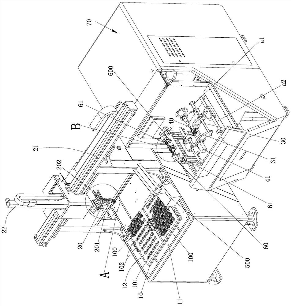
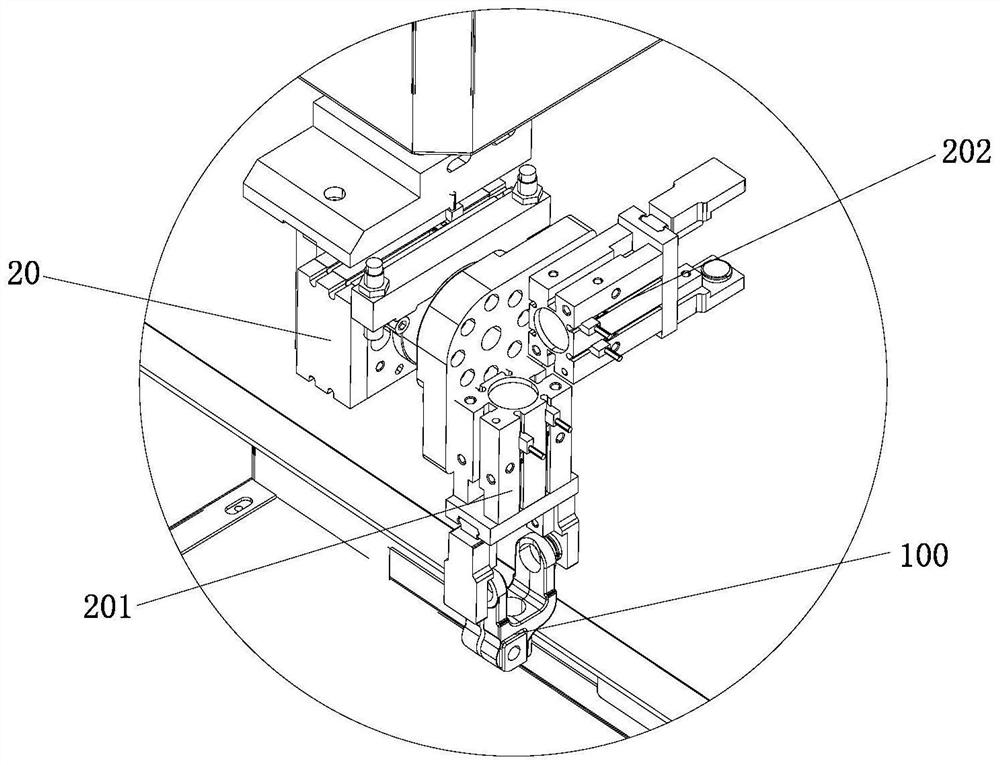
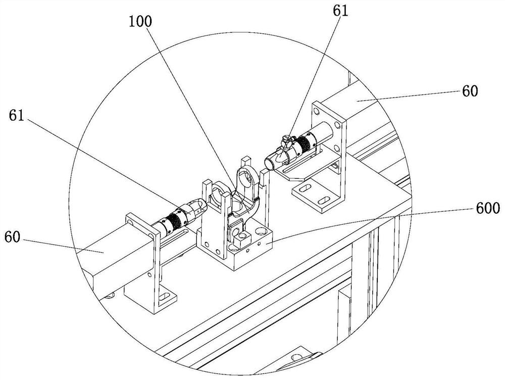
[0024] like Figure 1 to Figure 4 As shown, a component honing system, the honing system has transverse and longitudinal directions parallel to the horizontal plane and perpendicular to each other, the honing system includes an equipment rack, a honing mechanism arranged on the equipment rack for honing parts, and a honing mechanism arranged on the equipment rack. The loading and unloading mechanism on the frame, the honing mechanism includes a CNC honing machine 70, a clamping mechanism for supporting and positioning the parts, and the loading and unloading mechanism has a first placement area for placing the parts to be processed, and a second place for placing the processed parts. Two placement areas (the first placement area and the second placement area are located on the same side of the clamping mechanism in the transverse direct...


PUM


Abstract

The invention relates to a component honing system. The honing system has transverse and longitudinal directions parallel to a horizontal plane and perpendicular to each other. The honing system includes an equipment frame, a honing mechanism arranged on the equipment frame for honing parts, and a honing mechanism arranged on the equipment frame. The loading and unloading mechanism on the frame. The honing mechanism includes a CNC honing machine and a clamping mechanism for supporting and positioning the parts. The loading and unloading mechanism has a first placement area for placing the parts to be processed, and a second place for placing the processed parts. In the placement area, the loading and unloading mechanism also includes a conveying mechanism; in the component honing system of the present invention, through the cooperative design of the honing mechanism and the loading and unloading mechanism, the loading and unloading work of the honing of the components is automatically completed by the machine, without manual labor one by one. It can carry out loading and unloading operations without any problems, reduce the dependence on manual operation level and experience, greatly improve the production efficiency of honing and reduce production costs.

Description

technical field [0001] The invention relates to a component honing system. Background technique [0002] At present, honing is a process of finishing the finishing surface with honing sticks embedded on the honing head. In the prior art, a fork component on an automobile gearbox needs holes on both sides of the support arms. Carry out honing processing. In the prior art, the honing of the upper holes of the arms on both sides of the fork is carried out by manual loading and unloading. The forks are placed on the fixture one by one, and then a CNC honing machine is used for honing. After honing Then manually disassemble it, and send the processed fork to the detection device for hole diameter detection to judge whether it is qualified or not. The dependence on manual operation level and experience is very high, and the efficiency is very low. SUMMARY OF THE INVENTION [0003] The technical problem to be solved by the present invention is to overcome the deficiencies of th...

Claims


Application Information

Patent Timeline
Patent Type & Authority Patents(China)
IPC IPC(8): B24B33/02B24B33/10B24B33/06B24B41/06
CPCB24B33/02B24B33/10B24B33/06B24B41/005B24B41/06
Inventor 陈勇陈磊罗晓峰
Owner SUZHOU XINNENG PRECISE MACHINERY
Learn More