Traction beams and rail vehicles

A traction beam and sleeper beam technology, which is applied in the field of rail vehicles, can solve the problems of limited space for the design of the traction beam structure of the car body, large space, and the inability to make large changes to the bogie.

Active Publication Date: 2021-09-10
CRRC QINGDAO SIFANG CO LTD
View PDF6 Cites 0 Cited by
  • Summary
  • Abstract
  • Description
  • Claims
  • Application Information

AI Technical Summary

Problems solved by technology

[0002] At present, in the development and design process of straddle-type monorail trains, due to the special bogie structure that needs to occupy a large space, the design space of the traction beam structure of the car body is severely limited
The solution in the prior art is to optimize the structure of the bogie and reduce the space occupied by the bogie. However, due to the special operating conditions of the existing straddle-type monorail trains, the bogie cannot meet the requirements of the operating conditions. make more drastic changes
Therefore, in the existing straddle-type monorail trains, it is difficult to meet the space restriction requirements for the traction beam under the premise of satisfying the structural strength of the traction beam

Method used


Image

  • Traction beams and rail vehicles
  • Traction beams and rail vehicles
  • Traction beams and rail vehicles

Examples


Embodiment Construction

[0035] Embodiments of the present invention will be further described in detail below in conjunction with the accompanying drawings and examples. The following examples are used to illustrate the present invention, but should not be used to limit the scope of the present invention.

[0036]In the description of the embodiments of the present invention, it should be noted that the terms "center", "longitudinal", "transverse", "upper", "lower", "front", "rear", "left", "right" , "vertical", "horizontal", "top", "bottom", "inner", "outer" and other indicated orientations or positional relationships are based on the orientations or positional relationships shown in the drawings, and are only for the convenience of describing this The embodiments and simplified descriptions of the invention do not indicate or imply that the devices or elements referred to must have a specific orientation, be constructed and operate in a specific orientation, and therefore should not be construed as...


PUM


Abstract

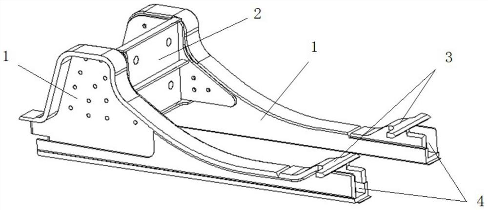
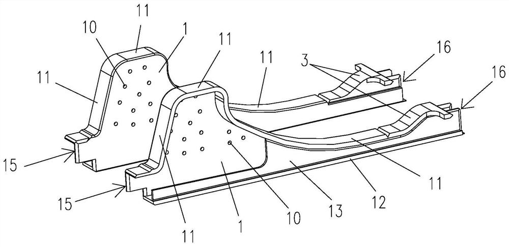
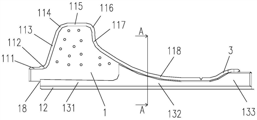
The invention relates to the technical field of rail vehicles and provides a traction beam and a rail vehicle. The traction beam includes two traction beam webs arranged oppositely at intervals, the upper side of each traction beam web is respectively connected with an upper flanging, and the lower side of each traction beam web is respectively connected with a lower flanging, and each traction beam web The outer sides of the traction beam are provided with a first reinforcing plate respectively, and the traction beam web, the upper flange, the first reinforcing plate and the lower flange are enclosed to form a load-bearing chamber; the first end of the traction beam web, the upper flange The buffer beam interface is formed between the first end of the first end of the first reinforcing plate and the first end of the lower flange; the second ends of each upper flange are respectively connected with connectors, and the second A corbel interface is formed between the end, the second end of the lower flange, the second end of the first reinforcing plate and the connecting piece. The present invention can simultaneously meet the space restriction requirements on the traction beam under the premise of satisfying the structural strength of the traction beam.

Description

technical field [0001] The invention relates to the technical field of rail vehicles, in particular to a traction beam and a rail vehicle. Background technique [0002] At present, in the R&D and design process of straddle-type monorail trains, due to the large space occupied by the special bogie structure, the design space of the traction beam structure of the car body is severely limited. The solution in the prior art is to optimize the structure of the bogie and reduce the space occupied by the bogie. However, due to the special operating conditions of the existing straddle-type monorail trains, the bogie cannot meet the requirements of the operating conditions. Make larger changes. Therefore, in the existing straddle-type monorail train, it is difficult to satisfy the space limitation requirement of the traction beam under the premise of satisfying the structural strength of the traction beam. Contents of the invention [0003] The present invention aims to solve at ...

Claims


Application Information

Patent Timeline
Patent Type & Authority Patents(China)
IPC IPC(8): B61F1/10B61G7/10B61G9/20B61F5/50
CPCB61F5/50B61G7/10B61G9/20
Inventor 闫立志郑伟刘鹏飞刘龙玺田洪雷
Owner CRRC QINGDAO SIFANG CO LTD
Why Eureka
Try Eureka