A pneumatic handling system

A handling system and pneumatic unit technology, applied in the directions of transportation and packaging, manual conveying devices, etc., can solve the problems of uncontrollable direction, uncontrollable handling, and inability to form, so as to ensure the ground area, support the bracket well, and cushion the impact. Effect

Active Publication Date: 2021-09-24
GUANGDONG YUANTIAN ENG
View PDF5 Cites 0 Cited by
  • Summary
  • Abstract
  • Description
  • Claims
  • Application Information

AI Technical Summary

Problems solved by technology

[0002] In real life, it is often necessary to transport large-volume and heavy-weight objects over short distances, such as equipment handling in engineering construction, position adjustment of factory equipment, etc. However, due to various conditions such as small indoor space, it is often impossible to use cranes, sky Cars, forklifts and other handling equipment, in order to solve the problem of short-distance handling, the traditional solution is: use a plurality of round rods to spread the ground, place the equipment on it, and push and pull the round rods by hand or crowbar to move forward. The effect of the method is poor, the speed is slow, the direction is uncontrollable, and it is easy to damage the ground. For uneven ground, because the round rod cannot be rotated, it cannot be transported
Another way is to use an air cushion truck to inflate the airbag to make it expand to form a ring. The air enters the air chamber from the airbag through the small hole, builds up the air bearing pressure in the air chamber, and deflates to the surroundings to form a ring on the ground. Very thin air film, due to the small frictional resistance of the air film, can use a small thrust to move the heavy object forward. This method requires manpower to push the heavy object forward, and has very high requirements for the flatness and smoothness of the ground. If the ground If it is uneven, it will not be able to carry due to the inability to form an effective air film

Method used


Image

  • A pneumatic handling system
  • A pneumatic handling system
  • A pneumatic handling system

Examples


Embodiment Construction

[0039] The present invention will be further described in detail in conjunction with the accompanying drawings and specific embodiments.

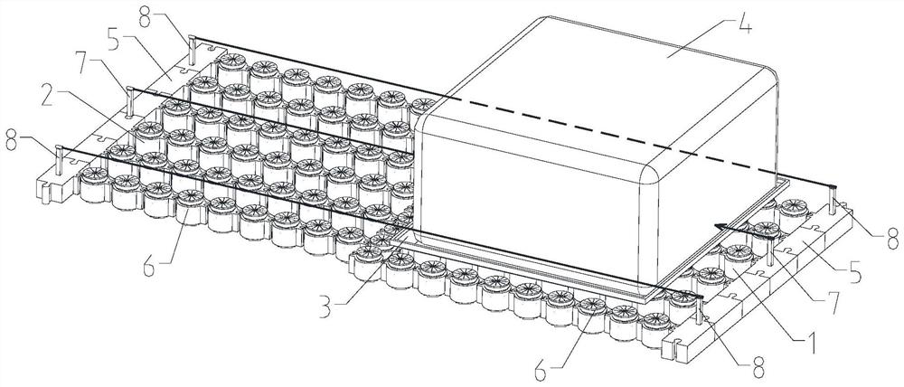
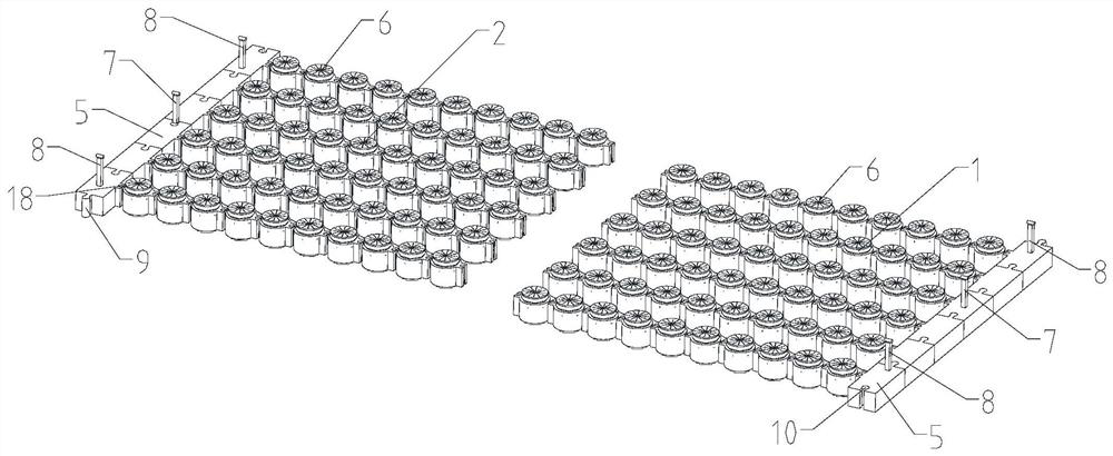
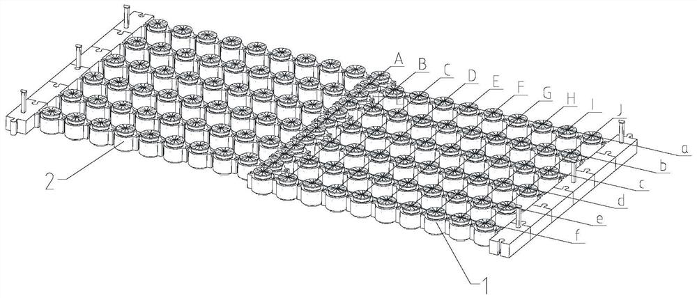
[0040] Such as Figure 1 to Figure 3 As shown, a pneumatic conveying system includes a bracket and a first conveying device and a second conveying device with the same structure. The first conveying device includes a plurality of sequentially connected control modules, and each control module is connected with a pneumatic unit ; The pneumatic unit of the second conveying device is misplaced with the pneumatic unit of the first conveying device, the bracket is located on the pneumatic unit of one of the conveying devices, and a heavy object is placed on the bracket; the control module is provided with a first controller and The wireless signal transmitter, the pneumatic unit is equipped with a second controller and a wireless signal receiver. The pneumatic unit can generate an air film to support the bracket. object handling.

[0041] Such...


PUM


Abstract

The present invention relates to the technical field of transport devices, in particular to a pneumatic transport system, which includes a bracket and a first transport device and a second transport device with the same structure. The first transport device includes a plurality of sequentially connected control modules, and each control module There is a row of pneumatic units connected to the top; the pneumatic unit of the second handling device and the pneumatic unit of the first handling device are misplaced, and the bracket is located on the pneumatic unit of one of the handling devices, and a heavy object is placed on the bracket; inside the control module A first controller and a wireless signal transmitter are provided, a second controller and a wireless signal receiver are provided in the pneumatic unit, the pneumatic unit can generate an air film to support the bracket, and the control module can control the airflow intensity ejected by the pneumatic unit, Thereby pushing the carriage forward to realize heavy object handling. The pneumatic unit of the invention can generate an air film at the bottom of the bracket to support the heavy objects, and push the bracket forward by controlling the strength of the airflow ejected from the pneumatic unit, so as to realize the transportation of the heavy objects.

Description

technical field [0001] The invention relates to the technical field of transport devices, in particular to a pneumatic transport system. Background technique [0002] In real life, it is often necessary to transport large-volume and heavy-weight objects over short distances, such as equipment handling in engineering construction, position adjustment of factory equipment, etc. However, due to various conditions such as small indoor space, it is often impossible to use cranes, sky Cars, forklifts and other handling equipment, in order to solve the problem of short-distance handling, the traditional solution is: use a plurality of round rods to spread the ground, place the equipment on it, and push and pull the round rods by hand or crowbar to move forward. The effect of the method is poor, the speed is slow, the direction is uncontrollable, and it is easy to damage the ground. For uneven ground, because the round rod cannot be rotated, it cannot be transported. Another way is...

Claims


Application Information

Patent Timeline
Patent Type & Authority Patents(China)
IPC IPC(8): B65G7/00
CPCB65G7/00
Inventor 曾杰华
Owner GUANGDONG YUANTIAN ENG
Why Eureka
Try Eureka