Vacuum welding furnace and welding technology

A vacuum welding furnace and welding chamber technology, which is applied in welding equipment, manufacturing tools, metal processing, etc., can solve the problems of low welding efficiency, slow cooling speed, downward bending, etc., and achieve reduced energy consumption, rapid heating and temperature Effect of cooling and avoiding sheet deformation

Active Publication Date: 2018-04-20
SHANDONG CAIJU ELECTRONICS TECH CO LTD
View PDF12 Cites 11 Cited by
  • Summary
  • Abstract
  • Description
  • Claims
  • Application Information

AI Technical Summary

Problems solved by technology

[0004] (1) There is only one heating zone that matches the vacuum processing device on the machine table. Since the material needs to be heated to a certain temperature to melt the solder paste and achieve the welding effect, the heating of the material requires time to move , resulting in a long heating time, and because the heating zone is set on the upper cover, the heating zone uses radiation to heat the material, and the heat transfer efficiency is low, which further increases the heating time of the material, making its welding efficiency low ;
[0005] (2) In order to facilitate the transmission of the material sheet by the transmission mechanism, both ends of the material sheet need to extend out of the carrying platform, and the transmission mechanism supports and transports the material sheet through the protruding parts of the two ends of the material sheet, because the heated material sheet is relatively soft , the protruding parts at both ends of the material will bend downwards, which will cause the position of the chips at both ends of the material to be unable to align with the contacts of the material, resulting in a large number of defective products;
[0006] (3) The temperature of the blanks after welding is too high and the cooling speed is slow. The blanks are easily oxidized after being removed from the vacuum processing device, and the temperature of the blanks removed from the machine is still too high, and workers cannot directly process the blanks.

Method used


Image

  • Vacuum welding furnace and welding technology
  • Vacuum welding furnace and welding technology
  • Vacuum welding furnace and welding technology

Examples


Embodiment Construction

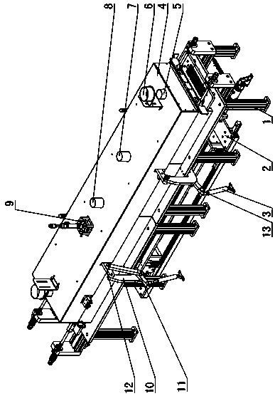
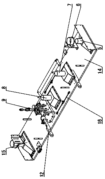
[0069] Figure 1~18 It is the best embodiment of the present invention, below in conjunction with the attached Figure 1~18 The present invention will be further described.

[0070] A vacuum welding furnace, comprising a welding chamber 18, a furnace cover 4 and a transport mechanism 2, the furnace cover 4 is covered on the upper side of the welding chamber 18, and a welding cavity is formed between the welding chamber 18 and the furnace cover 4, and the lower part of the welding chamber 18 A welding station 20 is provided, the side of the welding station 20 close to the feed end is a heating zone, the side of the welding platform 20 close to the discharge end is a cooling zone, and the upper side of the heating zone close to the cooling zone is provided with a negative pressure module 9 for pumping The negative pressure module 9 can be lifted and installed on the furnace cover 4. The bottom of the negative pressure module 9 and the heating zone are enclosed to form a closed ...


PUM


Abstract

The invention provides a vacuum welding furnace and a welding technology, and belongs to the technical field of vacuum welding. The vacuum welding furnace is characterized in that one end, close to the feeding end, of a welding platform (20) is used as a heating area; one side, close to the discharging end, of the welding platform (20) is used as a cooling area; a negative pressure pumping module(9) is arranged at the upper side of one end, close to the cooling area, of the heating area, and the negative pressure pumping module (9) is mounted on a furnace cover (4) by lifting; the bottom partof the negative pressure pumping module (9) and the heating area encircles a closed negative pressure chamber; a protecting gas inlet pipe is arranged on a welding chamber (18) or the furnace cover (4). According to the vacuum welding furnace, material sheets can be heated through the heating area, so that the material sheets can be quickly welded in the negative pressure chamber; protecting gasis charged, so that the material sheets are prevented from reacting with oxygen during being heated; the material sheets can be cooled and prevented from being oxidized through the cooling area. According to the welding technology, the welding time is decreased; the welding is accelerated; with the adoption of the cooling area, the material sheet can be completely cooled and is prevented from deformation caused by excessively quick cooling.

Description

technical field [0001] A vacuum welding furnace and a welding process belong to the technical field of vacuum welding. Background technique [0002] During the production of electronic components such as diodes, triodes, thyristors or bridges, chips need to be welded between the upper material and the lower material. This process is called bonding. The specific working process of the assembling is as follows: First, it is necessary to apply solder paste on the upper side of the lower material, and place the chip on the specific position of the lower material, and then stack the upper material with the solder paste on the lower side on the lower material. On the upper side of the sheet, cover the top cover of the welding mold on the bottom plate of the welding mold, and finally send the welding mold into the welding furnace for welding. The welding of blanks needs to be carried out in a vacuum furnace. [0003] The Chinese utility model patent with application number 201420...

Claims


Application Information

Patent Timeline
Patent Type & Authority Applications(China)
IPC IPC(8): B23K3/00B23K3/08B23K1/008
CPCB23K1/008B23K3/00B23K3/08B23K1/0016B23K3/0478
Inventor 李向东
Owner SHANDONG CAIJU ELECTRONICS TECH CO LTD
Why Eureka
Try Eureka