Continuous conveying mechanism for Pipe fittings

A technology of conveying mechanism and pipe fittings, which is applied in the directions of conveyors, conveyor objects, transportation and packaging, etc., can solve the problems of reducing the processing efficiency and quality of pipe fittings, adjusting the processing station of pipe fittings, and low feeding efficiency of pipe fittings, so as to improve the transmission efficiency. The degree of automation and the effect of reasonable structural design

Active Publication Date: 2020-12-04
玉环优智科技有限公司
View PDF5 Cites 2 Cited by
  • Summary
  • Abstract
  • Description
  • Claims
  • Application Information

AI Technical Summary

Problems solved by technology

During the production and processing of pipe fittings, it is necessary to sequentially load the pipe fittings that have been processed in the previous process to enable the processing of the subsequent process. After the existing pipe fittings have been processed in the previous process, in order to continue to process the pipe Production and processing, the existing method is to manually feed the pipe fittings one by one, the labor intensity of the workers is high, and the feeding efficiency of the pipe fittings is low, making it difficult to meet the needs of large-scale pipe fitting production and processing. It is difficult to adjust the processing position of the pipe fittings during the transfer and transfer process of the pipe fittings in turn. The existing pipe fitting station adjustment mainly uses the manipulator to grab and adjust the pipe fittings, but the manipulator is used for position adjustment. , first of all, it is necessary to grab the pipe fittings. In the process of grabbing the pipe fittings, the existing manipulators often cause the pipe fittings to fall off due to poor grasping during the process of grabbing the pipe fittings, resulting in the pipe fittings not being able to be processed normally. The processing of the process makes the efficiency and quality of pipe fittings processing not guaranteed, and in the process of using the manipulator to grab the pipe fittings, the manipulator needs multiple driving mechanisms to drive continuously and independently, the driving energy consumption is high, and multiple driving mechanisms It is also very prone to failure, it is difficult to run stably for a long period of time, and it cannot guarantee that the pipe fittings can be stably grabbed and placed one by one to the required station continuously and efficiently, making it difficult for the pipe fittings to be processed efficiently and accurately, and in the process of transferring the pipe fittings In the process, it is difficult to efficiently and smoothly turn the pipe fittings vertically and accurately, which makes it difficult to adjust the transfer station of the pipe fittings conveniently and accurately, which reduces the efficiency and quality of pipe fitting processing, and cannot meet the needs of processing and use.

Method used


Image

  • Continuous conveying mechanism for Pipe fittings
  • Continuous conveying mechanism for Pipe fittings
  • Continuous conveying mechanism for Pipe fittings

Examples


Embodiment Construction

[0011] In order to further describe the present invention, a specific implementation of a pipe continuous transmission mechanism will be further described below in conjunction with the accompanying drawings. The following examples are explanations of the present invention and the present invention is not limited to the following examples.

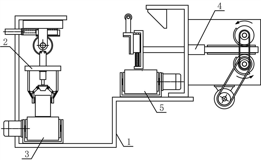
[0012] Such as figure 1 As shown, a continuous transmission mechanism for pipe fittings of the present invention includes a transmission bracket 1, an overturning mechanism 2, a front transmission mechanism 3, a pipe transfer mechanism 4 and a rear transmission mechanism 5, and the front transmission mechanism 3 is fixed horizontally on the lower side of the transmission bracket 1. The turning mechanism 2 is fixedly arranged on the transmission support 1 on the upper side of the front transmission mechanism 3, the rear transmission mechanism 5 is fixed horizontally on the upper side of the transmission support 1, and the pipe transfer mechan...


PUM


Abstract

The invention discloses a continuous conveying mechanism for pipe fittings, and belongs to the field of mechanical equipment for machining and conveying workpieces. A turnover mechanism of the continuous conveying mechanism disclosed by the invention is arranged on a conveying bracket arranged at the upper side of a front conveying mechanism; a straw moving mechanism is horizontally arranged on aconveying bracket arranged at the upper side of a rear conveying mechanism; a front straw conveying belt is horizontally arranged at the upper side of a front straw conveying bracket; a turnover connecting plate is fixedly arranged at one side of a turnover gear and in the radial direction of the turnover gear; a straw clamping mechanism is fixedly arranged at one side of the turnover connecting plate; a rear straw conveying belt is horizontally arranged at the upper side of a rear straw conveying bracket; a straw connecting plate is vertically arranged at one side of a translation bracket; atranslation guide plate at one side of the translation bracket is slidably arranged at a straw moving bracket and in the horizontal direction. The continuous conveying mechanism disclosed by the invention is reasonable in structural design, can be used for grabbing and turning over pipe fittings conveniently and efficiently, so that the pipe fittings are turned over from a vertical station to a horizontal station, and the pipe fittings can be adsorbed, transferred and accurately placed on the rear straw conveying belt to be conveyed, thus the automation degree of conveying of the pipe fittingsis improved, and the requirements of machining and use are met.

Description

technical field [0001] The invention belongs to the field of workpiece processing and conveying machinery, and in particular relates to a continuous conveying mechanism for pipe fittings, which is mainly used in the continuous translational conveying of pipe fittings. Background technique [0002] Pipe fittings refer to workpieces with a cylindrical structure. There are many types of pipe fittings. Different pipe fittings use different materials. The quality of the material directly determines the quality of the pipe fittings. Pipe fittings are necessary materials for construction engineering and mechanical equipment. A general term for components that play the roles of connection, control, direction change, flow diversion, sealing, support, etc. Steel pipe fittings are the most important type of pipe fittings. Steel pipe fittings are pressure-bearing pipe fittings. According to different processing techniques, steel pipe fittings can be divided into: butt welding pipe fitti...

Claims


Application Information

Patent Timeline
Patent Type & Authority Applications(China)
IPC IPC(8): B65G47/248B65G47/52B65G47/92
CPCB65G47/248B65G47/92B65G2201/0217B65G47/52
Inventor 陈怡
Owner 玉环优智科技有限公司
Why Eureka
Try Eureka