A yarn tension adjustment mechanism for two-for-one twisters in the textile industry

A technology of yarn tension and textile industry, applied in the field of yarn tension adjustment mechanism for double twister in textile industry, can solve the problems of unsatisfactory adjustment accuracy, poor stability of yarn tension adjustment mechanism, poor intuitiveness of yarn tension, etc. The adjustment accuracy is improved, the safety accident is avoided, and the synchronization is good.

Active Publication Date: 2021-10-08
QINGHAI DERUI TEXTILES IMPORT & EXPORT CO LTD
View PDF13 Cites 1 Cited by
  • Summary
  • Abstract
  • Description
  • Claims
  • Application Information

AI Technical Summary

Problems solved by technology

[0007] The object of the present invention is to provide a yarn tension adjustment mechanism for two-for-one twisters in the textile industry. By setting a lifting mechanism, a lifting plate, an air supply main pipe, an air intake branch pipe and an air discharge branch pipe, the tension adjustment roller is initially lifted by the lifting mechanism, In order to realize the rough adjustment of the tension, adjust the position of the lifting plate through air intake and deflation, and then adjust the position of the fourth bearing seat in the lifting box, realize further adjustment of the height of the tension adjustment roller, and realize fine adjustment and coarse adjustment of the tension. Combined with fine adjustment, the adjustment accuracy of the yarn tension is greatly improved, which solves the problems of poor stability, unsatisfactory adjustment accuracy and poor visibility of the yarn tension in the existing yarn tension adjustment mechanism

Method used


Image

  • A yarn tension adjustment mechanism for two-for-one twisters in the textile industry
  • A yarn tension adjustment mechanism for two-for-one twisters in the textile industry
  • A yarn tension adjustment mechanism for two-for-one twisters in the textile industry

Examples


Embodiment Construction

[0028] The following will clearly and completely describe the technical solutions in the embodiments of the present invention with reference to the accompanying drawings in the embodiments of the present invention. Obviously, the described embodiments are only some, not all, embodiments of the present invention. Based on the embodiments of the present invention, all other embodiments obtained by persons of ordinary skill in the art without creative efforts fall within the protection scope of the present invention.

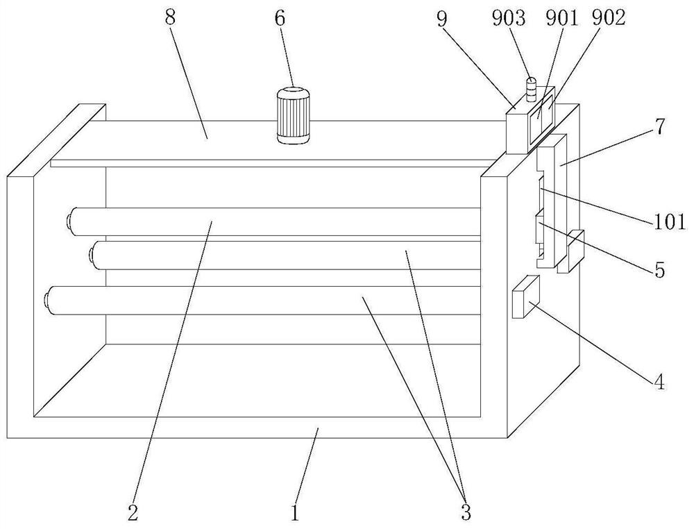
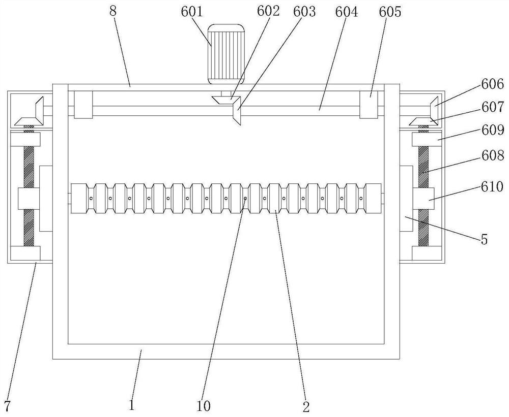
[0029] see figure 1 As shown, the present invention is a yarn tension regulating mechanism for a two-for-one twister in the textile industry, comprising a mounting frame 1, a tension regulating roller 2, a guide roller 3, a lifting box 5 and a lifting mechanism 6, and the inner middle end of the mounting frame 1 A tension adjustment roller 2 is provided, and guide rollers 3 are provided on the front and rear sides of the tension adjustment roller 2, and the two end...


PUM


Abstract

The invention discloses a yarn tension regulating mechanism for a two-for-one twister in the textile industry, and relates to the technical field of the textile industry. The invention includes a mounting frame, a tension regulating roller, a guide roller, a lifting box and a lifting mechanism. A tension regulating roller is arranged at the middle end of the mounting frame, and a guiding roller is arranged on both front and rear sides of the tension regulating roller. Both ends of the guiding roller They are respectively connected in rotation with the first bearing seat, the first bearing seat is fixed on the installation frame, and the two ends of the tension adjusting roller are respectively connected with the lifting box body. The present invention sets the lifting mechanism, the lifting plate, the gas main pipe, the air intake branch pipe and the air discharge branch pipe, and drives the tension adjusting roller to go up and down through the lifting mechanism, so as to realize the rough adjustment of the tension, and adjust the tension of the lifting plate through the air intake and deflation. Position, and then adjust the position of the fourth bearing seat in the lifting box to realize further adjustment of the height of the tension adjustment roller and fine adjustment of tension. The combination of coarse adjustment and fine adjustment greatly improves the adjustment accuracy of yarn tension.

Description

technical field [0001] The invention belongs to the technical field of the textile industry, in particular to a yarn tension regulating mechanism for a two-for-one twister in the textile industry. Background technique [0002] Twisted yarn is the process of twisting monofilaments or strands and intertwining multiple filaments to obtain a certain twist direction and number of twists. According to the requirements of the finished silk fabric specifications, the appearance effect of the yarn can be changed through the twisting process or The physical and mechanical properties can not only improve the weaving processing performance of the silk thread, but also meet the appearance of the fabric and the requirements of different uses. Twisting can increase the strength and wear resistance of the thread, so as to reduce fluff and broken ends, and improve the fastness of the silk fabric Twisted silk makes the silk thread have a certain shape or color, and gives the fabric appearance...

Claims


Application Information

Patent Timeline
Patent Type & Authority Patents(China)
IPC IPC(8): D01H13/10D01H13/14
CPCD01H13/102D01H13/14
Inventor 安定英马俊莉
Owner QINGHAI DERUI TEXTILES IMPORT & EXPORT CO LTD
Why Eureka
Try Eureka