
Support device for ultra-low temperature thermally decoupled turbine rotor

A supporting device and thermal decoupling technology, which is applied to components of pumping devices for elastic fluids, non-variable pumps, radial flow pumps, etc., can solve the problem of endangering the operation of compressor units and affecting the safe operation of compressors , Compressor rotor system instability and other issues, to achieve reliable fixation and support, prevent axial movement, and ensure consistency

Active Publication Date: 2021-12-14
上海电气控股集团有限公司 +3
View PDF0 Cites 0 Cited by
  • Summary
  • Abstract
  • Description
  • Claims
  • Application Information

AI Technical Summary

Problems solved by technology

When the temperature changes from normal temperature to ultra-low temperature, or from ultra-low temperature to normal temperature, or during the process of rapid temperature drop, the temperature gradient of each component of the compressor will be quite different. The local thermal stress is high, and the equipment is prone to damage after long-term operation, which will endanger the normal operation of the compressor unit
At the same time, due to the differences in the materials, fixed positions and temperature fields of each component, the elevation of the compressor rotor shaft system changes. When the change exceeds the allowable deflection range of the support structure, the compressor rotor system begins to lose stability, and the vibration intensifies, affecting compression. machine safe operation

Method used


Image

  • Support device for ultra-low temperature thermally decoupled turbine rotor
  • Support device for ultra-low temperature thermally decoupled turbine rotor
  • Support device for ultra-low temperature thermally decoupled turbine rotor

Examples


Embodiment Construction

[0033] The present invention will be further described below with reference to the accompanying drawings and specific examples.

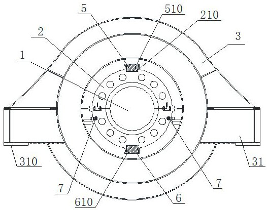
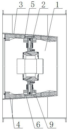
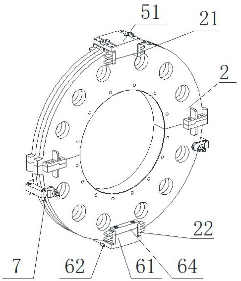
[0034] See figure 1 and 2 A support device for ultra-low thermal decoupling turning rotor, including a bearing box support 2, a top fixing assembly 5, a bottom fixing assembly 6, a clamping assembly 7, and an insulating assembly; an insulation assembly is disposed within the casing 3; See image 3 Attachment Image 6 The top of the bearing box support 2 is provided with a first key groove 21 that matches the top fixing assembly 5, and the bottom portion of the bearing box support 2 is provided with a second key slot 22 that matches the bottom fixing assembly 6, so that the bearing box The support body 2 is fixedly mounted within the casing 3 through the top fixing assembly 5 and the bottom fixing assembly 6, and the bearing box support 2 limits circumferential, horizontal, vertical and axial displacement by the top fixing assembly 5 and the bottom fixing ...


PUM


Abstract

The invention discloses a supporting device for an ultra-low temperature thermal decoupling turbine rotor, comprising a bearing housing support body (2), a top fixing component (5), a bottom fixing component (6), a clamping component (7) and a thermal insulation Components; the thermal insulation component is set in the casing (3); the bearing box support body is fixedly installed in the casing through the top fixing component and the bottom fixing component to limit its circumferential, horizontal, vertical and axial displacement; both sides of the casing There is a support part (31), and the support contact surface (310) of the support part is located in the same horizontal plane as the assembly contact surface of the bottom fixing component and the bearing box support body; a pair of clamping components are arranged in the casing and clamped symmetrically On both sides of the bearing box support body and limit its axial displacement. The invention can avoid the problem of thermal stress generated when the connecting parts of the compressor are operated in an ultra-low temperature environment, and can also ensure that the elevation of the shaft system of the compressor remains unchanged in different temperature fields.

Description

Technical field [0001] The present invention relates to a turbulent rotor mounting structure, and more particularly to a support device for ultra-low thermal decoupling turning rotor. Background technique [0002] The stability of the compressor rotor support structure is directly related to the safety and stability operation of the compressor, and it also directly affects the whole process of industrial production, especially the compressor running in ultra-low temperature environments (such as -196 ° C), in the industrial production process The middle continued high-speed operation, strictly requiring the stability of the rotor support structure. [0003] At present, the compressor rotor's support structure in the prior art uses the joint form of the flange bolt, and the compressor operated in the ultra-low temperature environment, considering the safety of the compressor, minimizes the effects of temperature on the compressor group, while To ensure the requirements of the stif...

Claims


Application Information

Patent Timeline
Patent Type & Authority Patents(China)
IPC IPC(8): F04D17/10F04D29/00F04D29/056F04D29/58F04D29/62
CPCF04D17/10F04D29/056F04D29/0563F04D29/5853F04D29/624F04D29/002
Inventor 徐宇峰聂徐庆洪兴福顾恒庆周恩民卢世承周俊超闻翔
Owner 上海电气控股集团有限公司
Learn More