Clutch and clutch pressure plate assembly

A clutch and pressure plate technology, applied in clutches, friction clutches, mechanical drive clutches, etc., can solve the problems of difficult replacement, inflexible maintenance and operation, and achieve the effect of avoiding displacement, flexible structure and convenient operation.

Inactive Publication Date: 2020-12-04
湖北三丰汽配有限公司
View PDF0 Cites 0 Cited by
  • Summary
  • Abstract
  • Description
  • Claims
  • Application Information

AI Technical Summary

Problems solved by technology

[0004] The purpose of the present invention is to provide a clutch and a clutch pressure plate assembly to solve the problem that the structure of the clutch and the pressure plate assembly of the clutch is not easy to replace and the maintenance operation is not flexible enough in the above-mentioned background technology

Method used


Image

  • Clutch and clutch pressure plate assembly
  • Clutch and clutch pressure plate assembly
  • Clutch and clutch pressure plate assembly

Examples


Embodiment Construction

[0024] The following will clearly and completely describe the technical solutions in the embodiments of the present invention with reference to the accompanying drawings in the embodiments of the present invention. Obviously, the described embodiments are only some, not all, embodiments of the present invention.

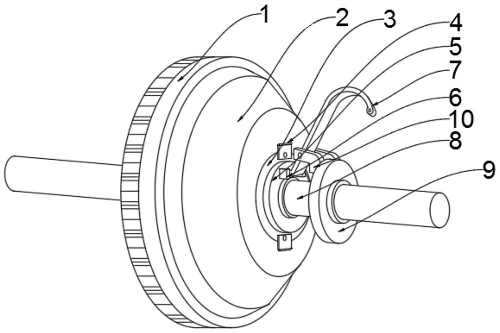
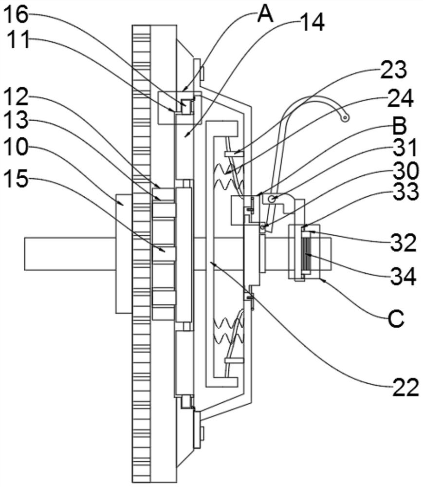
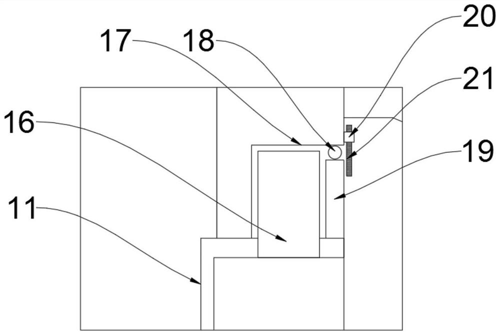
[0025] see Figure 1-5 , an embodiment provided by the present invention: a clutch and clutch pressure plate assembly, including a flywheel 1, the front end of the flywheel 1 is provided with a housing 2, the front end of the housing 2 is provided with a connection port 3, and the front surface of the housing 2 is provided with a symmetrical first A movable rod 4, a connecting seat 5 is provided at the front end of the connecting port 3, a symmetrical fixed plate 6 is provided at the front end of the connecting seat 5, a transmission rod 7 is arranged between the two fixed plates 6, and a connecting seat 5 is provided between the flywheel 1 and the connecting seat 5. ...


PUM


Abstract

The invention discloses a clutch and a clutch pressure plate assembly, relates to the technical field of clutches and clutch pressure plates, and aims to solve the problems that structures of an existing clutch and a clutch pressure plate assembly are not liable to be replaced and the maintenance operation is not flexible enough. A shell is arranged at the front end of a flywheel, a connecting port is formed in the front end of the shell, symmetrical first movable rods are arranged on the surface of the front end of the shell, a connecting base is arranged at the front end of the connecting port, symmetrical fixing plates are arranged at the front end of the connecting base, and a transmission rod is arranged between the two fixing plates. A rotating shaft is arranged between the flywheeland the connecting base, a fixing base is arranged in the rotating shaft and located in front of the flywheel, symmetrical clamping plates are arranged at the front end of the fixing base, a first groove is formed in the front end of the flywheel, and a second groove is formed in the first groove.

Description

technical field [0001] The invention relates to the technical field of clutches and clutch pressure plates, in particular to a clutch and clutch pressure plate assembly. Background technique [0002] The clutch is located in the flywheel housing between the engine and the gearbox. The clutch assembly is fixed on the rear plane of the flywheel with screws. The output shaft of the clutch is the input shaft of the gearbox. When the car is running, the driver can step on it as needed. Depress or release the clutch pedal to temporarily separate the engine from the gearbox and gradually engage it to cut off or transmit the power input from the engine to the transmission. The clutch pressure plate is an essential part of the assembly, just like the brake on the wheel. Like the moving plate, it is made of very wear-resistant asbestos and copper wire. The friction plate of the pressure plate also has a minimum allowable thickness. After a long mileage, the friction plate on the press...

Claims


Application Information

Patent Timeline
Patent Type & Authority Applications(China)
IPC IPC(8): F16D13/70F16D13/58
CPCF16D13/58F16D13/70
Inventor 夏泽顺何振王巧平潘献文
Owner 湖北三丰汽配有限公司
Why Eureka
Try Eureka