Sealing valve for solid-liquid mixing conveying pipeline

A technology for conveying pipelines and solid-liquid mixing, applied in sliding valves, valve devices, engine components, etc., can solve the problems of inconvenient control and connection, use impact, and inconvenient use, and achieve the effect of preventing weak connections and facilitating transmission.

Pending Publication Date: 2020-12-04
杜华为
View PDF9 Cites 0 Cited by
  • Summary
  • Abstract
  • Description
  • Claims
  • Application Information

AI Technical Summary

Problems solved by technology

[0003] However, the current valve body structure has some problems during use. The most prominent problem is that it is inconvenient to adjust and connect in the solid-liquid mixed delivery pipeline, which will affect the use and cause inconvenience in use. Convenience question

Method used


Image

  • Sealing valve for solid-liquid mixing conveying pipeline
  • Sealing valve for solid-liquid mixing conveying pipeline
  • Sealing valve for solid-liquid mixing conveying pipeline

Examples


Embodiment Construction

[0028] The following will clearly and completely describe the technical solutions in the embodiments of the present invention with reference to the accompanying drawings in the embodiments of the present invention. Obviously, the described embodiments are only some, not all, embodiments of the present invention. Based on the embodiments of the present invention, all other embodiments obtained by persons of ordinary skill in the art without making creative efforts belong to the protection scope of the present invention.

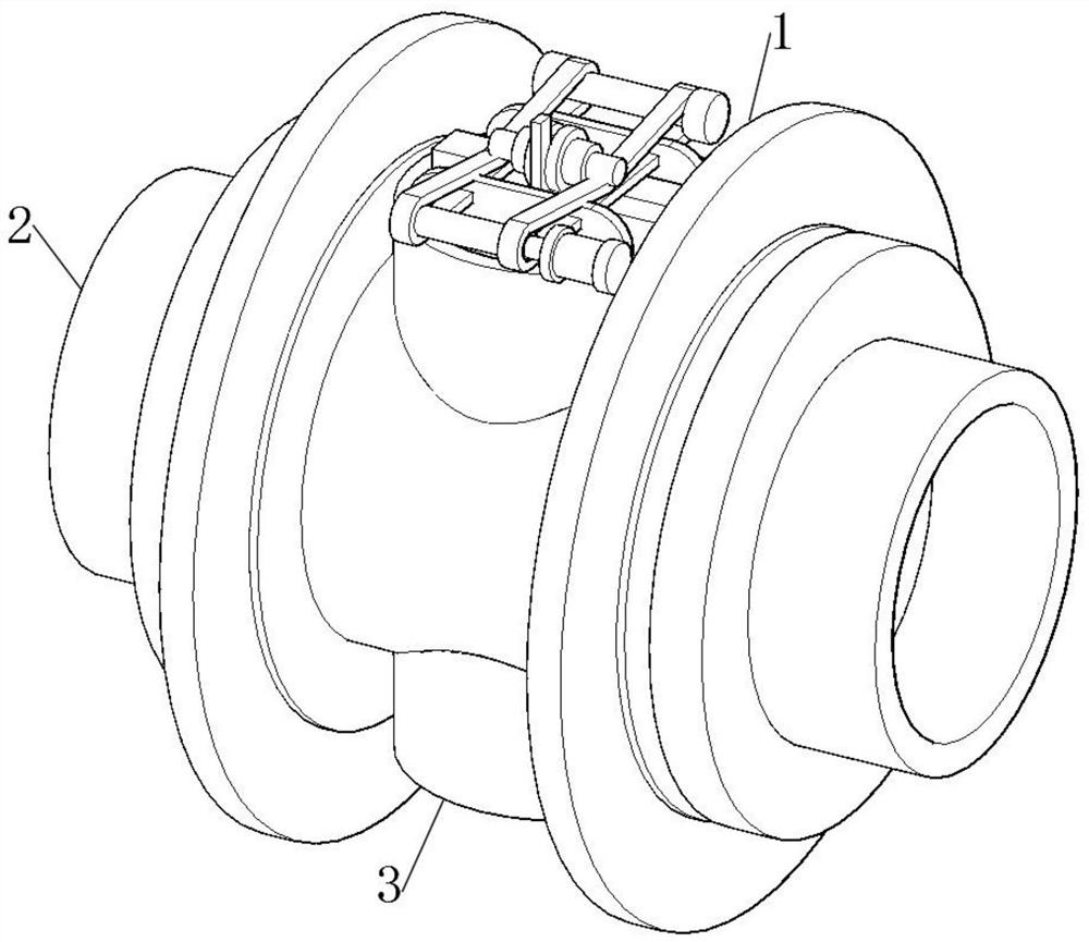
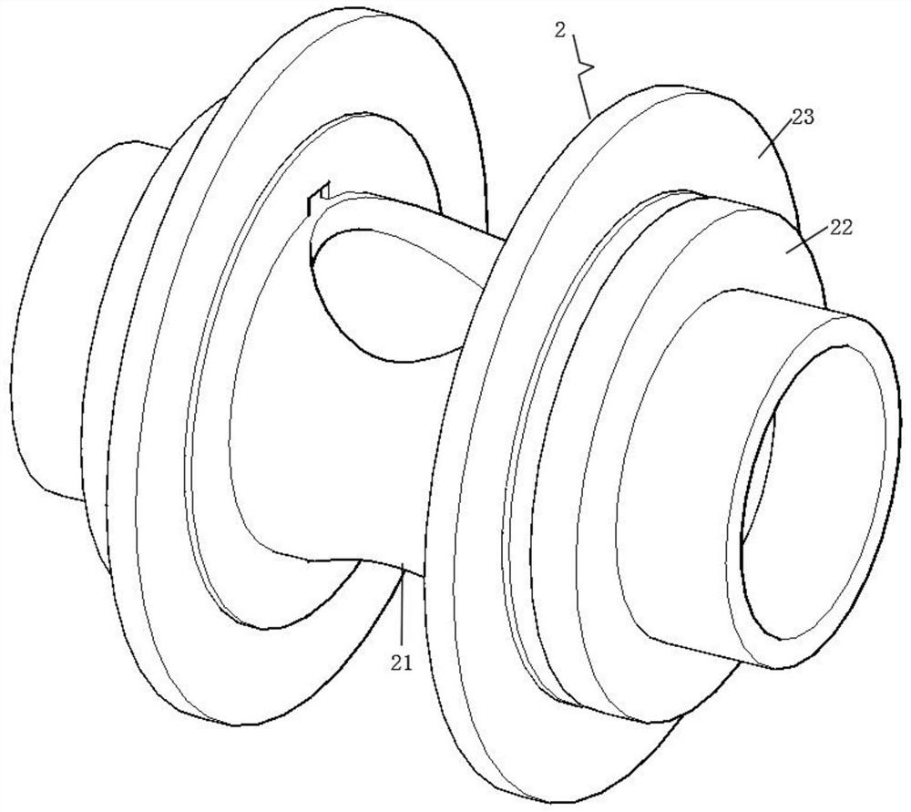
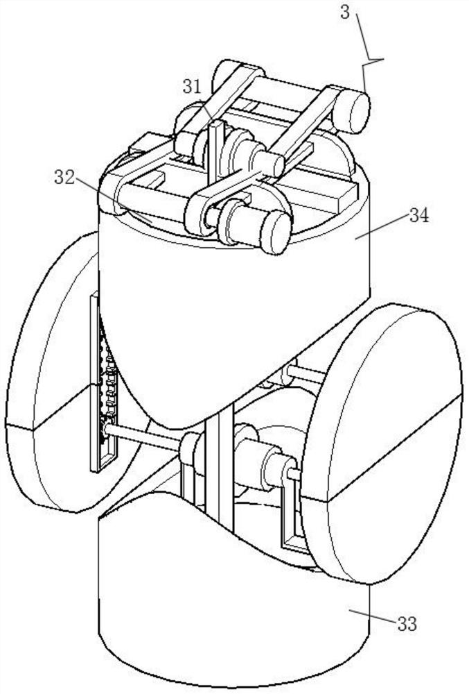
[0029] see Figure 1-6, the present invention provides a technical solution: a sealing valve for a solid-liquid mixing pipeline, including a sealing valve body 1, a pipe body 2 is provided at the center of the inner end of the sealing valve body 1, and the longitudinal position of the pipe body 2 is connected through a The valve structure 3, the pipe body 2 and the outer wall of the valve structure 3 are welded and fixed, and the sealing valve body 1 is instal...


PUM


Abstract

The invention relates to the technical field of sealing valve equipment, in particular to a sealing valve for a solid-liquid mixing conveying pipeline. The sealing valve comprises a sealing valve mainbody, wherein a pipe body is arranged in the center of the inner end of the sealing valve main body, a valve structure is connected to the longitudinal position of the pipe body in a penetrating manner, and the pipe body is fixedly welded to the outer wall of the valve structure. According to the sealing valve for the solid-liquid mixing conveying pipeline, through the arrangement of the valve structure, the purpose of regulating and controlling the valve at the inner end is achieved.

Description

technical field [0001] The invention relates to the technical field of sealing valve equipment, in particular to a sealing valve for a solid-liquid mixing pipeline. Background technique [0002] The current valve body structure adopts a soft-sealed gate valve, and the soft-sealed gate valve is divided into two types: a bright-stem soft-sealed gate valve and a dark-stem soft-sealed gate valve. Usually there is a trapezoidal thread on the lifter, and through the nut in the middle of the gate and the guide groove on the valve body, the rotating motion is changed into a straight line motion, that is to say, the operating torque is changed into the operation thrust. When the valve is opened, when the lifting height of the gate plate is equal to 1:1 times the diameter of the valve, the passage of the fluid is completely unblocked, but during operation, this position cannot be monitored. In actual use, the apex of the valve stem is used as a sign , that is, the position that does ...

Claims


Application Information

Patent Timeline
IPC IPC(8): F16K3/02F16K3/314
CPCF16K3/0254F16K3/02F16K3/314
Inventor 杜华为王明
Owner 杜华为
Why Eureka
Try Eureka