Built-in control rod driving wire mounting method

An installation method and drive line technology, applied in the control of nuclear reactions, reactors, reduction of greenhouse gases, etc., can solve problems such as reducing loading and unloading work and maintenance work efficiency, affecting device safety, reliable operation, and difficulty in ensuring safety and reliability, etc. , to achieve the effect of guaranteeing safety and reliability, reliable assembly, and simple assembly method

Pending Publication Date: 2020-12-04
TSINGHUA UNIV
View PDF0 Cites 1 Cited by
  • Summary
  • Abstract
  • Description
  • Claims
  • Application Information

AI Technical Summary

Problems solved by technology

However, the loading and unloading method of the built-in control rod drive line in the prior art is inconvenient for installation and operation, which not only reduces the efficiency of loading and unloading w

Method used


Image

  • Built-in control rod driving wire mounting method
  • Built-in control rod driving wire mounting method
  • Built-in control rod driving wire mounting method

Examples


Embodiment Construction

[0071] In order to make the purpose, technical solutions and advantages of the embodiments of the present invention clearer, the technical solutions in the embodiments of the present invention will be clearly and completely described below in conjunction with the drawings in the embodiments of the present invention. Obviously, the described embodiments It is a part of embodiments of the present invention, but not all embodiments. Based on the embodiments of the present invention, all other embodiments obtained by persons of ordinary skill in the art without creative efforts fall within the protection scope of the present invention.

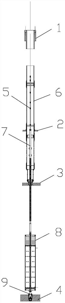
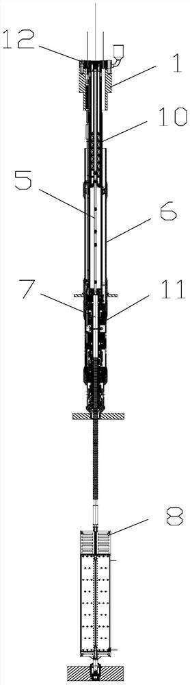
[0072] Such as Figure 1 to Figure 5 As shown, the embodiment of the present invention provides a method for installing a built-in control rod driving line, and the method mainly includes an initial installation stage, a first installation stage, a second installation stage, and a third installation stage.

[0073] Such as figure 1 As shown, in ...


PUM


Abstract

The invention relates to the technical field of built-in control rod driving, and provides a built-in control rod driving line mounting method. According to the method, a spring box component and a driving mechanism component are assembled to form a driving line assembly, the driving line assembly is hoisted into a driving line guide cylinder, and a driving shaft of a control rod component is locked through a spring box buffer lock. The method is convenient to assemble, the efficiency of loading and unloading work and maintenance work is improved, the safety and reliability of the installationand operation process can be guaranteed, and then safe and reliable operation of the built-in control rod driving line after assembly is guaranteed.

Description

technical field [0001] The invention relates to the technical field of built-in control rod driving, in particular to a method for installing a built-in control rod driving line. Background technique [0002] In the built-in control rod driving technology, the driving mechanism needs to be placed in the high temperature, high pressure and irradiation environment in the reactor pressure vessel, and three hydraulic cylinders are used to lift, transfer and clamp in order to drive the transmission and clamp two sets of pins The claw mechanism moves to realize the functions of step-up, step-down and drop of the control rod. [0003] Based on the working principle of the driving mechanism and the characteristics of the small integrated water reactor control rod drive line, the built-in control rod drive line is required for safe and reliable assembly and disassembly operations on the integrated small water reactor. However, the loading and unloading method of the built-in control...

Claims


Application Information

Patent Timeline
IPC IPC(8): G21C7/16
CPCG21C7/16Y02E30/30
Inventor 薄涵亮姜胜耀张亚军秦本科赵陈儒刘潜峰王金海
Owner TSINGHUA UNIV
Why Eureka
Try Eureka