Electromagnetic coil

A technology of electromagnetic coils and wires, applied in transformer/inductor coils/windings/connections, circuits, electrical components, etc. The effect of sustainable development and cost saving

Pending Publication Date: 2020-12-04
王浩然
View PDF0 Cites 0 Cited by
  • Summary
  • Abstract
  • Description
  • Claims
  • Application Information

AI Technical Summary

Problems solved by technology

[0005] In order to make up for the deficiencies of the existing technology, solve the problem that the electromagnetic coil and the installation base are fixedly connected by dispensing glue in the prior art, resulting in damage to the electromagnetic coil or components that cannot be recycled after being burned, resulting in waste, and the problem of the bottom of the coil with different sizes. The distance between the ends of the wires is not equal, so different types of coils need to match the corresponding base plate, the applicability of the base plate is low, and this will increase the production cost. An electromagnetic coil proposed by the present invention

Method used


Image

  • Electromagnetic coil
  • Electromagnetic coil
  • Electromagnetic coil

Examples


Embodiment approach

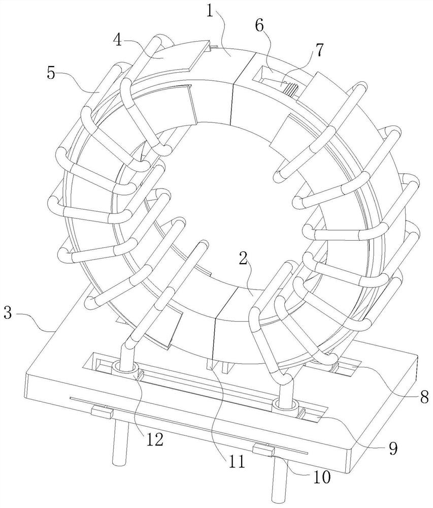
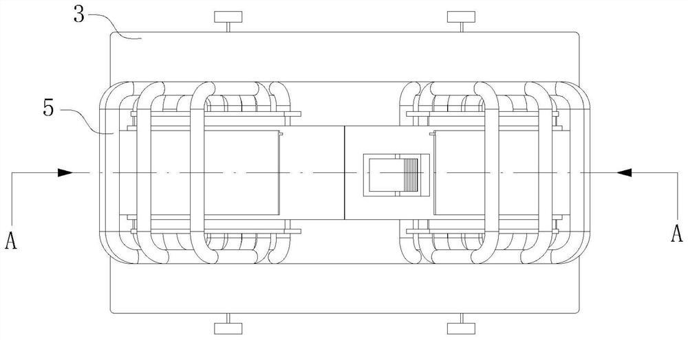
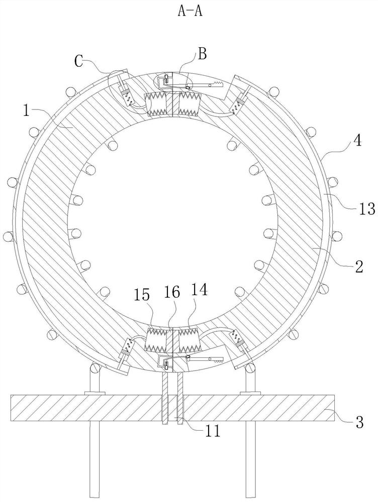
[0036] As an embodiment of the present invention, the gas control device includes a storage groove 14, a first spring compression tube 15, a push rod 25, a cylindrical cavity 26 and a piston plate 27; the storage groove 14 is located at the left arc winding The end of the rod 1 and the end of the right arc-shaped winding rod 2; the bottom of the receiving groove 14 is fixedly connected with one end of the first spring compression tube 15; the other end of the first spring compression tube 15 is connected with the compression The surface of the block 16 is fixed; the bottom of the first spring compression tube 15 communicates with the cylindrical cavity 26 located inside the left arc winding rod 1 and the right arc winding rod 2; the cylindrical cavity 26 is close to One end of the receiving groove 14 is fixedly connected with one side of the piston plate 27 through a spring; the other side of the piston plate 27 is fixedly connected with one end of the push rod 25; and the out...


PUM


Abstract

The invention belongs to the technical field of electromagnetic coils, and particularly relates to an electromagnetic coil which comprises a left arc-shaped winding rod, a right arc-shaped winding rodand a mounting bottom plate. The end parts of the left arc-shaped winding rod and the right arc-shaped winding rod are spliced with each other, clamping blocks fixedly arranged at the two ends of theright arc-shaped winding rod are inserted into the clamping grooves at the end parts of the left arc-shaped winding rod, and arc-shaped supporting plates are movably arranged on the outer walls, thefront sides and the rear sides of the left arc-shaped winding rod and the right arc-shaped winding rod through gas control devices. According to the present invention, the end of a wire is clamped inthe threading groove in a lower pressing plate, then a coil can be fixed to the upper surface of the mounting bottom plate, compared with a traditional four-point dispensing fixing mode, on one hand,fixing can be completed without dispensing equipment, then the cost can be saved, and on the other hand, when the coil is damaged or burnt out, the coil can be detached from the mounting bottom plate,so that the left arc-shaped winding rod and the right arc-shaped winding rod can be separated, and the wire can be easily detached.

Description

technical field [0001] The invention belongs to the technical field of electromagnetic coils, in particular to an electromagnetic coil. Background technique [0002] Electromagnetic coils are also called inductance coils, and inductance coils are devices that use the principle of electromagnetic induction to work. When a current flows through a wire, a certain electromagnetic field will be generated around the wire, and the wire itself of this electromagnetic field will induce the wire within the range of this electromagnetic field. The effect on the wire itself that generates the electromagnetic field is called "self-inductance", that is, the changing current generated by the wire itself produces a changing magnetic field, and this magnetic field further affects the current in the wire; the effect on other wires in the range of this electromagnetic field , called "mutual inductance". [0003] The electrical characteristics of the inductance coil are opposite to those of t...

Claims


Application Information

Patent Timeline
IPC IPC(8): H01F27/30H01F27/29H01F27/06H01F27/28
CPCH01F27/306H01F27/29H01F27/06H01F27/2823H01F27/2828
Inventor 王浩然王陆军
Owner 王浩然
Why Eureka
Try Eureka