Intelligent monitoring center display equipment placement device

A display device, intelligent monitoring technology, applied in electrical equipment shell/cabinet/drawer, cabinet/box/drawer parts, cleaning methods and utensils, etc. Service life and other issues, to achieve the effect of blocking external dust, protecting from external damage, and facilitating viewing

Active Publication Date: 2021-10-29
广东翰锋科技有限公司
View PDF0 Cites 0 Cited by
  • Summary
  • Abstract
  • Description
  • Claims
  • Application Information

AI Technical Summary

Problems solved by technology

[0003] In order to make up for the above deficiencies, the present invention provides an intelligent monitoring center display device placement device, which aims to improve the existing placement device. The placement device is relatively simple, and the display is mostly exposed, easily damaged by external forces, and easy to enter the problem of dust affecting the service life.

Method used


Image

  • Intelligent monitoring center display equipment placement device
  • Intelligent monitoring center display equipment placement device
  • Intelligent monitoring center display equipment placement device

Examples


Embodiment 1

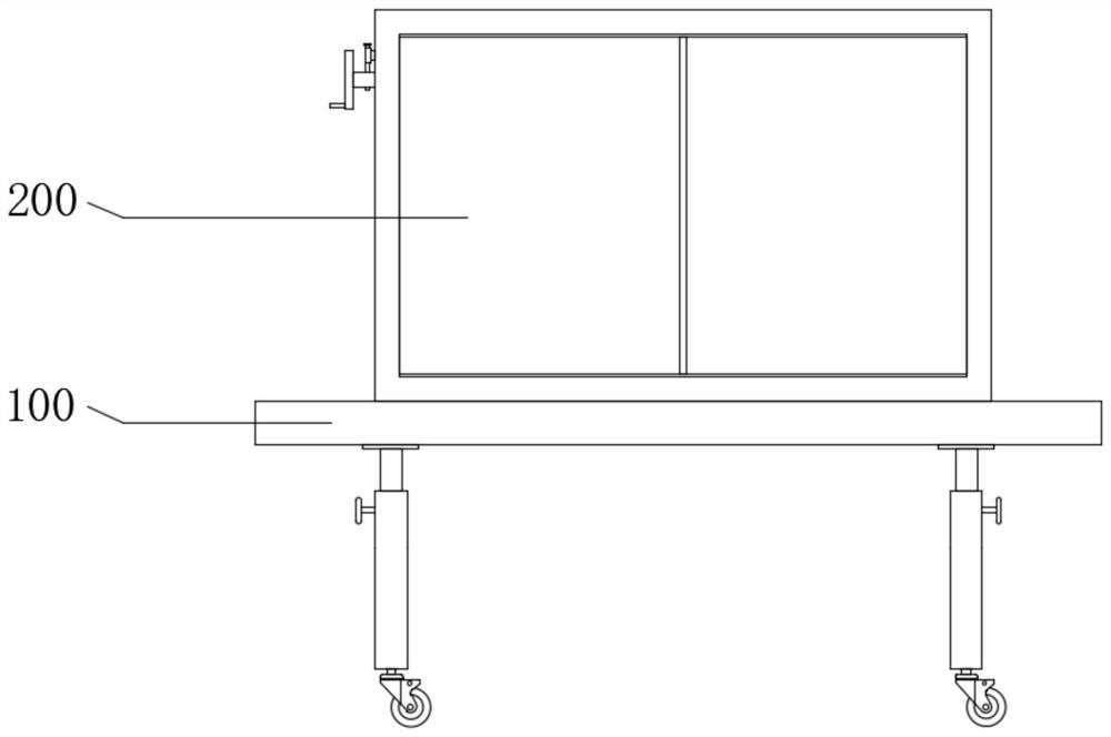
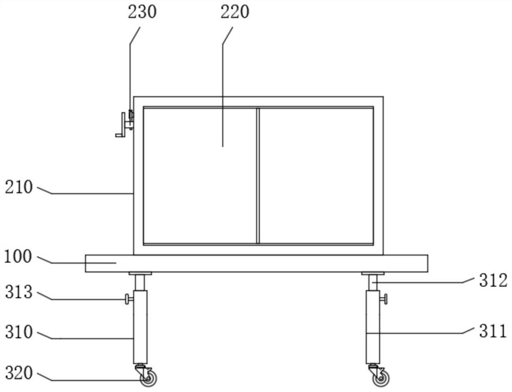
[0034] see Figure 1-7 , the present invention provides a technical solution: an intelligent monitoring center display device placement device includes a base 100 and a placement assembly 200 .

[0035] The base 100 is used to support the placement assembly 200, and the placement assembly 200 is used to place the display device while protecting the display device and prolonging its service life.

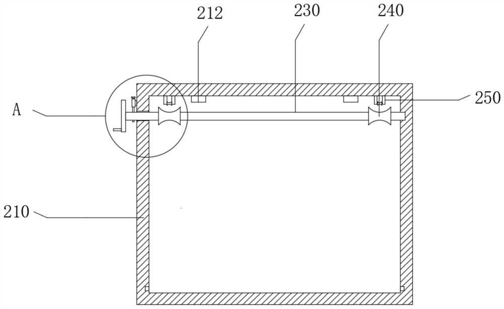
[0036] see figure 1 , 2, 3, 4, 5, 6 and 7, the placement assembly 200 includes a housing 210, a placement plate 220, a rotating shaft 230, a drum 240, a support 250, a steel wire rope 260 and a fixed plate 270, and one side of the housing 210 is hollowed out, and the housing 210 is mounted on the top of the base 100, the housing 210 is bolted or welded to the base 100, and one end of the placement plate 220 is rotatably connected to the inner bottom of the housing 210. Specifically, the outer bottom of the placement plate 220 is provided with a pin shaft 224, and the pin shaft 224 ...

Embodiment 2

[0038] see Figure 1-7 , the present invention provides a technical solution: an intelligent monitoring center display device placement device includes a base 100 and a placement assembly 200 .

[0039] The base 100 is used to support the placement assembly 200, and the placement assembly 200 is used to place the display device while protecting the display device and prolonging its service life.

[0040] see figure 1 , 2 , 3, 4, 5, 6 and 7, the placement assembly 200 includes a housing 210, a placement plate 220, a rotating shaft 230, a drum 240, a support 250, a steel wire rope 260 and a fixed plate 270, and one side of the housing 210 is hollowed out, and the housing 210 is mounted on the top of the base 100, the housing 210 is bolted or welded to the base 100, and one end of the placement plate 220 is rotatably connected to the inner bottom of the housing 210. Specifically, the outer bottom of the placement plate 220 is provided with a pin shaft 224, and the pin shaft 224...


PUM


Abstract

The invention provides a display device placement device for an intelligent monitoring center, and belongs to the technical field of display device placement. The placement device for display equipment in the intelligent monitoring center includes a base and a placement assembly, the placement assembly includes a housing, a placement board, a rotating shaft, a drum, a support, a wire rope and a fixing plate, one side of the housing is hollowed out, and the housing Installed on the top of the base, one end of the placement plate is rotatably connected to the inner bottom of the housing, the rotating shaft is rotatably arranged on the inner top of the housing, two drums are provided, and the drums are fixedly sleeved on The surface of the rotating shaft, the support member is fixedly connected to the side of the housing close to the rotating shaft, one end of the wire rope is wound on the surface of the drum, and the display device is placed on the placement board and then stored into the housing The body, thus effectively blocking the external dust, while largely protecting the display device from external damage.

Description

technical field [0001] The invention relates to the field of placement devices, in particular to a display device placement device for an intelligent monitoring center. Background technique [0002] A display device can also be called a display, or directly and popularly called a display screen, a screen, and the like. It is a device that can output images or sensory information. If the input signal is an electronic signal, this display device will be called an electronic display device, as opposed to a mechanical display device. The monitoring center needs to install corresponding display equipment for monitoring. Some existing installations for display equipment have a relatively simple structure, and the display equipment is mostly exposed, which is easily damaged by external forces and dust, which affects the service life. Contents of the invention [0003] In order to make up for the above deficiencies, the present invention provides an intelligent monitoring center...

Claims


Application Information

Patent Timeline
Patent Type & Authority Patents(China)
IPC IPC(8): H05K5/02B08B17/02
CPCB08B17/025H05K5/0217H05K5/0234
Inventor 来宝根
Owner 广东翰锋科技有限公司
Why Eureka
Try Eureka