
Steel bar bending device

A technology for bending and bending of steel bars, applied in the field of steel structure processing equipment, can solve the problems of inconvenient use, easy to be damaged, occupying a large construction space, etc.

Inactive Publication Date: 2020-12-08
六安长城钢结构有限公司
View PDF6 Cites 0 Cited by
  • Summary
  • Abstract
  • Description
  • Claims
  • Application Information

AI Technical Summary

Problems solved by technology

For the bending of steel bars, the more traditional method is mainly operated manually, but manual bending of steel bars not only consumes a lot of manpower, but also takes up a lot of construction space, which not only affects the safety of the construction site, but also must Affected the progress of the project to a certain extent
Some construction sites also use steel bar bending machines, but the existing steel bar bending machines cannot control the bending angle of steel bars well, and the bending angle is fixed, so the scope of application is narrow; some existing steel bar bending machines use intelligent control, but the construction site The surrounding environment and the operating level of the construction personnel make this kind of steel bar bending machine poor in practicability and easy to be damaged, which causes great inconvenience to people.

Method used


Image

  • Steel bar bending device
  • Steel bar bending device
  • Steel bar bending device

Examples


Embodiment Construction

[0020] The present invention will be described in detail below with reference to the accompanying drawings and in combination with embodiments.

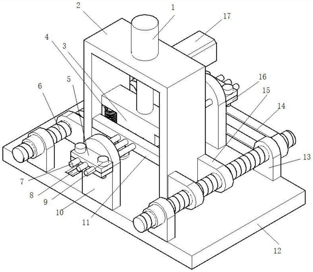
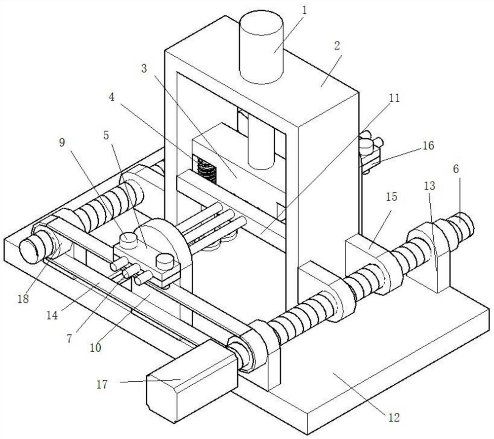
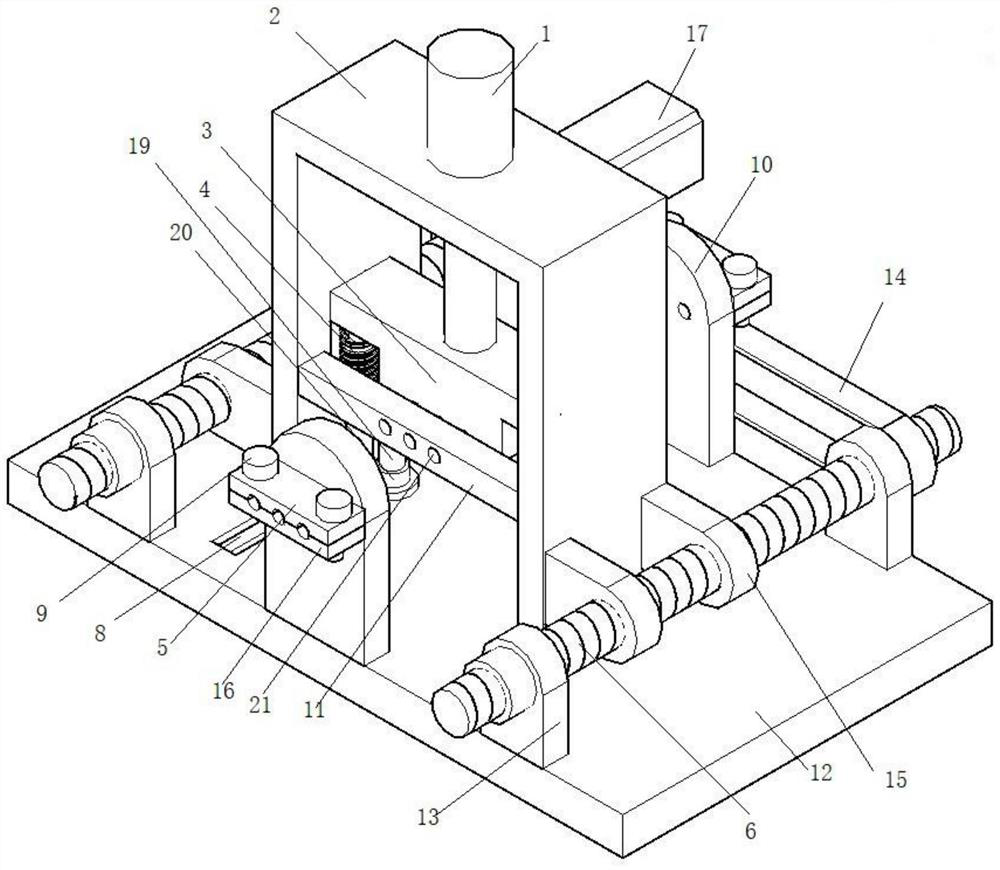
[0021] Such as Figures 1 to 5 As shown, this embodiment provides a steel bar bending device, including a bottom plate, a support plate is fixed at the center of the bottom plate, and a sliding frame that is movably installed on the bottom plate is provided between the two support plates. Both sides of the sliding frame are provided with drivers fixedly installed on the base plate, and the inside of the sliding frame is provided with a bending plate movably installed on the sliding frame and driven by a cylinder. The bottom of the bending plate is provided with There is a support structure fixed on the base plate.

[0022] Place the steel bar on the support plate, and clamp the steel bar through the screw, the upper clamping plate and the lower clamping plate, the motor drives the screw to rotate, and drives the sliding frame to mov...


PUM


Abstract

The invention discloses a steel bar bending device. The steel bar bending device comprises a bottom plate, wherein two supporting plates are fixedly arranged at the center of the bottom plate; a sliding frame movably arranged on the bottom plate is arranged between the two supporting plates; drivers fixedly arranged on the bottom plate are arranged on two sides of the sliding frame; a bending plate movably arranged on the sliding frame and driven by a cylinder is arranged in the sliding frame; and the bottom of the bending plate is provided with a supporting structure fixed on the bottom plate. In use, a steel bar is arranged on the supporting plates, and is clamped through screws, an upper clamping plate and a lower clamping plate, a motor drives a screw rod to rotate, the sliding frame is driven to move along a sliding groove, consequently, the purpose of adjusting the bending position is achieved, after the position is adjusted, the cylinder drives a plate body to move downwards tobend the steel bar, and the bending angle of the steel bar is controlled through controlling the downward movement distance of the plate body according to requirements.

Description

technical field [0001] The invention relates to the technical field of steel structure processing equipment, in particular to a steel bar bending device. Background technique [0002] With the gradual development of my country's economic construction, large-scale construction projects are being carried out all over the country to build various residential buildings, office buildings, road works and other projects under construction. Large quantities of steel bars are bent. For the bending of steel bars, the traditional method is mainly manual operation, but manual bending of steel bars not only consumes a lot of manpower, but also takes up a lot of construction space, which not only affects the safety of the construction site, but also must affected the progress of the project to a certain extent. Some construction sites also use steel bar bending machines, but the existing steel bar bending machines cannot control the bending angle of steel bars well, and the bending angle...

Claims


Application Information

Patent Timeline
IPC IPC(8): B21F1/00
CPCB21F1/004
Inventor 柳建新鲍杰杜金龙孙成会张道刚柳豪李文杰闫晓军
Owner 六安长城钢结构有限公司
Learn More