
Pneumatic-control rigidity-variable two-finger manipulator

A variable stiffness and manipulator technology, applied in the field of manipulators, can solve problems such as the inability to accurately control the bending angle of the fingers of the manipulator, and achieve the effect of improving operability and stability

Active Publication Date: 2021-12-07
ANHUI UNIVERSITY
View PDF6 Cites 0 Cited by
  • Summary
  • Abstract
  • Description
  • Claims
  • Application Information

AI Technical Summary

Problems solved by technology

[0003] After searching, the Chinese patent application number is CN202010531123.3, which discloses a soft manipulator with the function of active variable stiffness, including body fingers, bracket, flexible belt drive mechanism, main air pipe, cross and hose; the lower part of the bracket The surface is uniformly provided with three soft fingers along the circumferential direction, and the upper surface of the bracket is uniformly provided with three flexible belt drive mechanisms along the circumferential direction, and each soft finger corresponds to a flexible belt drive mechanism, and the center of the upper surface of the support is provided with a Hollow-out frame; however, the above technical solution only bends the fingers of the manipulator by pulling the flexible belt, so there is still the problem that the bending angle of the fingers of the manipulator cannot be precisely controlled

Method used


Image

  • Pneumatic-control rigidity-variable two-finger manipulator
  • Pneumatic-control rigidity-variable two-finger manipulator
  • Pneumatic-control rigidity-variable two-finger manipulator

Examples


Embodiment Construction

[0030] The technical solution of this patent will be further described in detail below in conjunction with specific embodiments.

[0031] Embodiments of the present patent are described in detail below, examples of which are shown in the drawings, wherein the same or similar reference numerals designate the same or similar elements or elements having the same or similar functions throughout. The embodiments described below by referring to the figures are exemplary and are only used for explaining the patent, and should not be construed as limiting the patent.

[0032]In the description of this patent, it is to be understood that the terms "center", "upper", "lower", "front", "rear", "left", "right", "vertical", "horizontal", The orientation or positional relationship indicated by "top", "bottom", "inner", "outer", etc. is based on the orientation or positional relationship shown in the drawings, and is only for the convenience of describing this patent and simplifying the desc...


PUM


Abstract

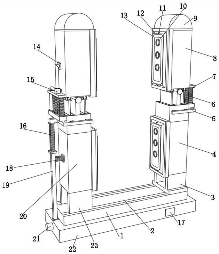
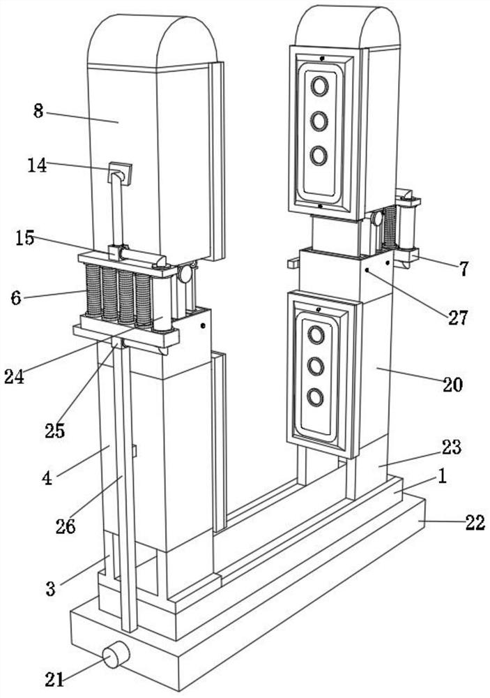
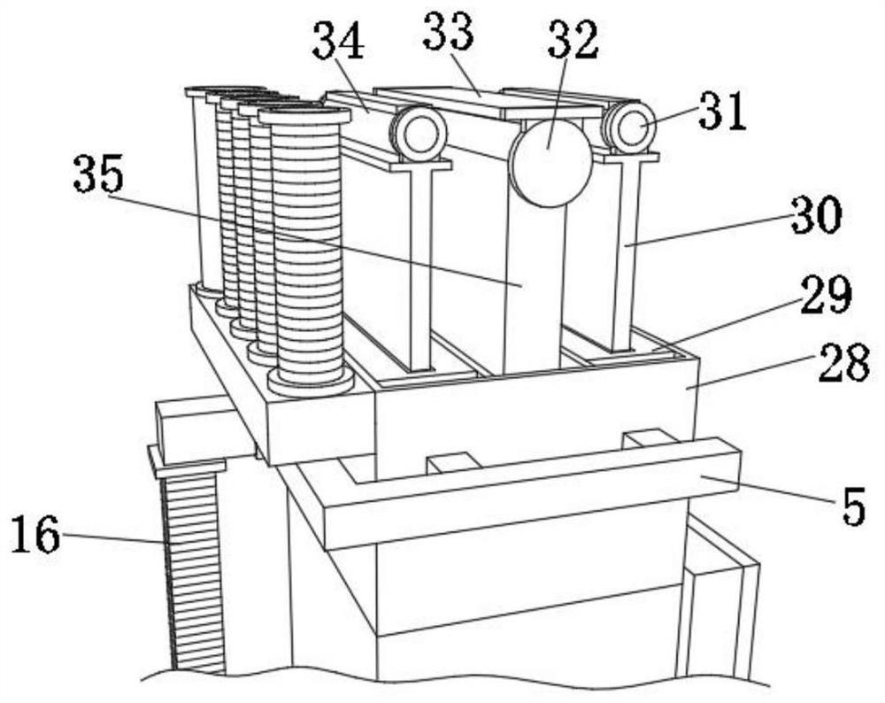
The invention discloses a pneumatic-control rigidity-variable two-finger manipulator and relates to the technical field of manipulators. By means of the pneumatic-control rigidity-variable two-finger manipulator, the problem that the finger bending angle of the manipulator cannot be accurately controlled is solved. The pneumatic-control rigidity-variable two-finger manipulator specifically comprises a mounting plate, a connecting plate is fixed to the outer wall of the bottom of the mounting plate, two connecting valves are fixed to the outer walls of the two sides of the connecting plate, a first finger section and a third finger section are arranged on the outer wall of the top of the mounting plate, and a second air supply pipe and a third air supply pipe are fixed to the outer wall of the top of the connecting plate. According to the pneumatic-control rigidity-variable two-finger manipulator, by means of the arrangements of air cylinders, push plates, a connecting circular ring, a rotating column, a connecting disc and a fixing block, when a second finger section needs to be bent, a worker can control the corresponding air cylinder to push one push plate to move upwards and control the other air cylinder to drive the corresponding push plate to move downwards by the same distance at the same time, and at the moment, the rotating column and the fixed block are driven by the two push plates to rotate through the connecting circular ring, so that the second finger section connected with the top of the rotating column and the top of the fixed block is inclined.

Description

technical field [0001] The invention relates to the technical field of manipulators, in particular to an air-controlled variable stiffness two-finger manipulator. Background technique [0002] With the rapid development of robot technology, the manipulator is playing an increasingly important role as the end gripping device of the robot. The manipulator is also called the end effector or the gripper. It is a part installed on the robot arm to directly grasp the object or perform the operation. It has the functions of clamping, transporting, and placing the workpiece to a certain position. The dexterity of the manipulator has a major impact on the success or failure of robot applications, and has become a key issue restricting the development of the robot industry. The difficulty in the study of manipulator dexterity lies in the integration of drive, transmission, sensor and electrical system in a limited space, and it also needs to adapt to different working environments an...

Claims


Application Information

Patent Timeline
IPC IPC(8): B25J15/00B25J15/08
CPCB25J15/00B25J15/0009B25J15/08
Inventor 孙先涛王辰陈文杰陈伟海胡存刚陶骏
Owner ANHUI UNIVERSITY
Learn More