Unlock instant, AI-driven research and patent intelligence for your innovation.

A 3D printing scanning filling path planning method for thin-walled parts

A 3D printing and path planning technology, applied in the field of 3D printing, can solve the problems of difficult to form a printing path, a gap at the geometric center, poor surface morphology at the corner, etc., to achieve short idle travel, improve processing efficiency, and optimize corners Effect

Active Publication Date: 2021-03-16
南京衍构科技有限公司
View PDF5 Cites 0 Cited by
  • Summary
  • Abstract
  • Description
  • Claims
  • Application Information

AI Technical Summary

Problems solved by technology

At present, the reciprocating straight line method or the offset contour method are mostly used to generate the scanning and filling path; please refer to Figure 5 As shown in , the scanning line fills in a Z shape along the direction of the angle between the coordinate axis. When using the reciprocating straight line method to generate a filling path for complex polygons, it is difficult to form a continuous printing path, and the surface morphology at the corner is poor; please refer to Image 6 As shown in , the offset contour filling along the direction perpendicular to the contour, when using the offset contour method to generate the filling path, because the polygon shape and filling width cannot guarantee to completely fill the entire contour area, it is easy to form a gap at the geometric center
[0003] The traditional arc fuse additive manufacturing technology usually uses the teaching method for path planning, which is suitable for products with simple structures and regular shapes; for variable cross-section components, it is very difficult to use the teaching method for path planning

Method used


Image

  • A 3D printing scanning filling path planning method for thin-walled parts
  • A 3D printing scanning filling path planning method for thin-walled parts
  • A 3D printing scanning filling path planning method for thin-walled parts

Examples


Embodiment Construction

[0041] The following will clearly and completely describe the technical solutions in the embodiments of the present invention with reference to the accompanying drawings in the embodiments of the present invention. Obviously, the described embodiments are only some, not all, embodiments of the present invention. Based on the embodiments of the present invention, all other embodiments obtained by persons of ordinary skill in the art without creative efforts fall within the protection scope of the present invention.

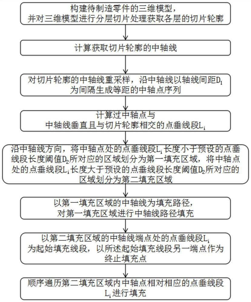
[0042] see Figure 1-4 As shown, the present invention is a 3D printing scanning filling path planning method for thin-walled parts, comprising the following steps:

[0043] Step 1: Construct a three-dimensional model of the part to be manufactured, and perform layered slice processing on the three-dimensional model to obtain the slice outline of each layer;

[0044] Step 2: Calculate and obtain the central axis of the slice contour;

[0045] The central axis is a ...


PUM


Abstract

The invention discloses a 3D printing scanning filling path planning method for a thin-walled workpiece, and relates to the technical field of 3D printing. According to the method, a slice contour isdivided into a first filling area and a second filling area by judging whether a point vertical line segment on a central axis point sequence is larger than a preset point vertical line segment lengththreshold D2 or not, and then distinguishing filling is conducted. The method comprises the following steps of judging whether the point vertical line segment on the central axis point sequence is greater than a preset point vertical line segment length threshold D2 or not, and dividing the slice contour into the first filling area and the second filling area; filling the first filling area witha central axis path; and connecting point vertical line segments in the second filling area through line segments, forming a continuous filling path through arc curve transition, and then performing path filling. The method is suitable for manufacturing single-connected parts; compared with a parallel scanning path, the idle stroke is short, and the machining efficiency is improved; and compared with an offset scanning path, a cavity is prevented from appearing in the center of the contour, the idle stroke is small, and stable transition of the scanning speed is achieved by optimizing corners.

Description

technical field [0001] The invention belongs to the technical field of 3D printing, in particular to a 3D printing scanning filling path planning method for thin-walled parts. Background technique [0002] In the additive manufacturing technology, the scanning and filling path planning of the 3D model layered slicing contour is one of the key technologies. At present, the reciprocating straight line method or the offset contour method are mostly used to generate the scanning and filling path; please refer to Figure 5 As shown in , the scanning line fills in a Z shape along the direction of the angle between the coordinate axis. When using the reciprocating straight line method to generate a filling path for complex polygons, it is difficult to form a continuous printing path, and the surface morphology at the corner is poor; please refer to Image 6 As shown, the offset contour filling along the direction perpendicular to the contour, when using the offset contour method to...

Claims


Application Information

Patent Timeline
Patent Type & Authority Patents(China)
IPC IPC(8): B29C64/386B29C64/10B33Y10/00B33Y50/00
CPCB33Y10/00B33Y50/00B29C64/10B29C64/386
Inventor 吴玲珑张召远许春权
Owner 南京衍构科技有限公司