Steel strand lifting device for slide-moving tool

A steel strand and tooling technology, which is applied in the field of steel strand lifting devices, can solve problems such as stability problems, unsafe pressure holding, and easy oil leakage, etc., so as to prevent breakage or damage, prolong service life, and improve safety sexual effect

Pending Publication Date: 2020-12-08
中交三航(南通)海洋工程有限公司
View PDF0 Cites 0 Cited by
  • Summary
  • Abstract
  • Description
  • Claims
  • Application Information

AI Technical Summary

Problems solved by technology

[0003] (1) The jacking stroke is relatively small. After all, the piston rod of the oil cylinder is used for direct support. The piston rod is very long, and the overall stability is problematic and unsafe;
[0004] (2) The self-weight of the sliding tooling is relatively large, the size of the jacking cyl

Method used


Image

  • Steel strand lifting device for slide-moving tool
  • Steel strand lifting device for slide-moving tool
  • Steel strand lifting device for slide-moving tool

Examples


Embodiment Construction

[0022] In order to deepen the understanding of the present invention, the present invention will be further described below in conjunction with the embodiments and accompanying drawings. The embodiments are only used to explain the present invention and do not constitute a limitation to the protection scope of the present invention.

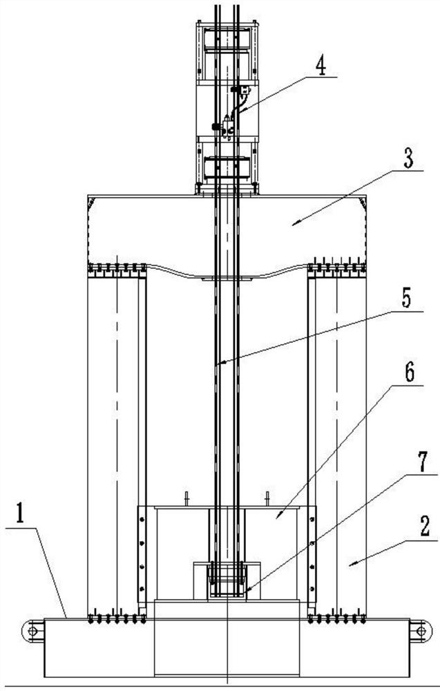
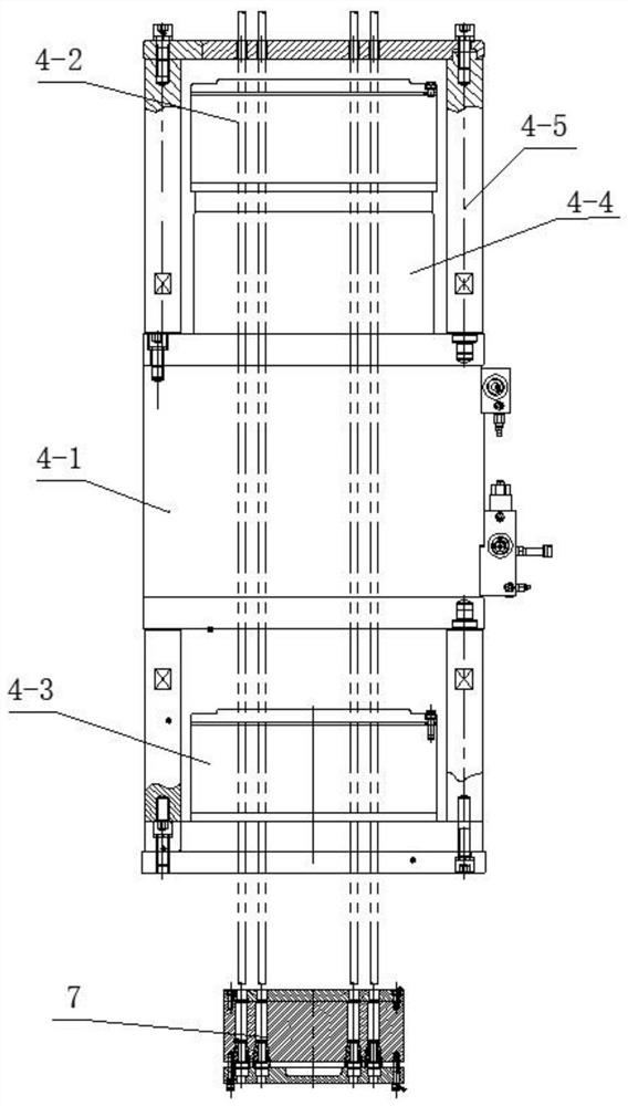
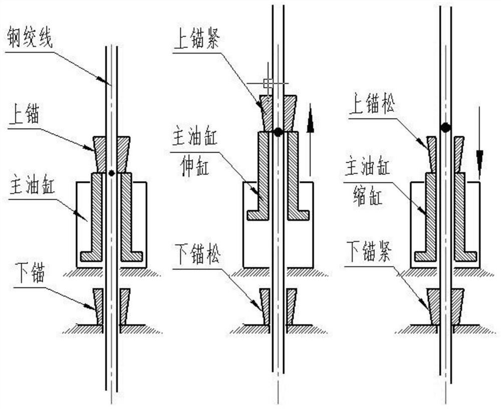
[0023] Such as Figure 1-Figure 3 It shows a specific embodiment of a steel strand lifting device used for sliding tooling: it includes a bottom plate 1, a supporting column 2, a top beam 3, a lifting cylinder 4 and a steel strand 5, and symmetrically arranged on the bottom plate 1. There are supporting columns 2, and the tops of the two supporting columns 2 are jointly connected with a top beam 3, a lifting cylinder 4 is arranged on the top beam 3, and a load beam 6 is arranged on the bottom plate 1. The anchor seat 7 is fixed by bolts in the square groove of the beam 6, and the lifting cylinder 4 and the anchor seat 7 are connected by a steel s...


PUM


Abstract

The invention discloses a steel strand lifting device for a slide-moving tool. The steel strand lifting device comprises a bottom plate, supporting stand columns, a top cross beam, a lifting oil cylinder and a steel strand, the supporting stand columns are symmetrically arranged on the bottom plate, the tops of the two supporting stand columns are jointly connected with the top cross beam, the lifting oil cylinder is arranged on the top cross beam, and a bearing beam is arranged on the bottom plate. An anchor seat is fixed in a square groove of the bearing beam through bolts, and the lifting oil cylinder is connected with the anchor seat through the steel strand. According to the steel strand lifting device, the steel strand is used for lifting, so that the lifting stroke is increased, theoccupied area is small, the lifting capacity is high, and the steel strand lifting device has the advantages that the self-locking of the steel strand is realized, the oil cylinder can be unloaded only by locking an anchorage device after being lifted to a required height, the safety is improved, and the service life of the steel strand is prolonged.

Description

Technical field: [0001] The invention relates to the technical field of workpiece lifting, in particular to a steel strand lifting device for sliding tooling. Background technique: [0002] At present, the lifting devices of commonly used sliding tooling are all hydraulically lifted, and the oil cylinder is mainly used for direct lifting. This method has the following disadvantages: [0003] (1) The jacking stroke is relatively small. After all, the piston rod of the oil cylinder is used for direct support. The piston rod is very long, and the overall stability is problematic and unsafe; [0004] (2) The self-weight of the sliding tooling is relatively large, the size of the jacking cylinder is relatively large, and the overall structure is very large; [0005] (3) The sliding time of the sliding tooling is long, and it is not safe to use the oil cylinder to keep the pressure for a long time under heavy load, and oil leakage is prone to occur during the sliding process, whi...

Claims


Application Information

Patent Timeline
IPC IPC(8): B66F7/04B66F7/28
CPCB66F7/04B66F7/28
Inventor 唐建明华军明汪峥
Owner 中交三航(南通)海洋工程有限公司
Why Eureka
Try Eureka