Centrifugal spinning frame

A spinning frame, centrifugal technology, applied in the spinning machine, continuous winding spinning machine, textile and papermaking, etc., can solve the problem of increasing the suction force, the function of the yarn sensor, and the optimization of the position of the suction tube Difficulties and other issues, to achieve the best effect of the position

Active Publication Date: 2022-07-05
TOYOTA IND CORP
View PDF8 Cites 0 Cited by
  • Summary
  • Abstract
  • Description
  • Claims
  • Application Information

AI Technical Summary

Problems solved by technology

If the amount of air injection in the suction bobbin is increased, the suction force can be increased, but energy loss due to increased air consumption will occur
In addition, if the yarn suction tube is placed near the bottom roller of the draft device in order to increase the success rate of yarn suction by the yarn suction tube, the function of the yarn sensor will be hindered, and the suction efficiency of the air nozzle will decrease.
Therefore, it is very difficult to optimize the position of the suction tube

Method used


Image

  • Centrifugal spinning frame
  • Centrifugal spinning frame
  • Centrifugal spinning frame

Examples


Embodiment Construction

[0023] Hereinafter, embodiments of the present invention will be described in detail with reference to the accompanying drawings.

[0024]

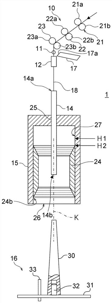
[0025] figure 1 It is a schematic diagram which shows the structural example of the centrifugal spinning frame which concerns on embodiment of this invention.

[0026] Furthermore, in figure 1 In the figure, the structure of each part of the centrifugal spinning frame is shown in a simplified manner, and the actual shape and size may be different.

[0027] like figure 1 As shown, the centrifugal spinning frame 1 includes a draft device 10 , a yarn sensor 11 , a pneumatic nozzle 17 , a yarn suction bobbin 12 , a yarn guide bobbin 14 , a tank 15 , and a bobbin support portion 16 . Further, these constituent elements constitute one spindle as one unit of spinning. The centrifugal spinning frame 1 includes a plurality of spindles, but the configuration of one of the spindles will be described here.

[0028] (Drafting device)

[0029] ...


PUM


Abstract

The present invention provides a centrifugal spinning frame capable of optimizing the position of the suction bobbin. The centrifugal spinning frame is provided with a yarn suction bobbin (12) for sucking the yarn drawn by the drafting device (10), a cylindrical tank (15), and the yarn supplied through the yarn suction bobbin (12) to the tank (12). 15) A yarn guide tube guided inside, the centrifugal spinning frame is provided with a yarn suction tube (12) supported so as to be movable in the direction of the central axis of the tank (15), and the position of the yarn suction tube (12) is switched to a suction position (P1) and the suction bobbin driving part (52) which is closer to the spinning position (P2) of the tank (15) than the suction position.

Description

technical field [0001] The present invention relates to a centrifugal spinning frame. Background technique [0002] As a spinning frame, a centrifugal spinning frame using a cylindrical tank is known. In a centrifugal spinning frame, the tank is rotated at a predetermined speed, and the yarn (fiber bundle) drawn by the drafting device is guided into the tank through a yarn guide tube, and the yarn is wound around the inner wall of the tank to form gauze. In addition, when the formation of the yarn cake is completed, the yarn is cut on the upstream side of the yarn guide tube, and then the yarn tube is inserted into the can to rewind the yarn from the inner wall of the can to the yarn tube. [0003] In the centrifugal spinning frame, a yarn suction bobbin is arranged on the upstream side of the yarn guide tube, and the yarn is introduced into the yarn guide tube through the yarn suction tube (for example, refer to Patent Document 1). The yarn suction tube sucks the yarn se...

Claims


Application Information

Patent Timeline
Patent Type & Authority Patents(China)
IPC IPC(8): D01H1/08
CPCD01H1/08
Inventor 宫田康广富永直路中村祐介
Owner TOYOTA IND CORP
Why Eureka
Try Eureka