Movable assembling frame for assembled wall
A technology of assembly frame and mobile frame, which is applied in the direction of construction, building structure, and building material processing, etc. It can solve the problems of low efficiency, low assembly efficiency, dumping, etc., and achieve the effect of high fine-tuning accuracy and convenient operation
- Summary
- Abstract
- Description
- Claims
- Application Information
AI Technical Summary
Problems solved by technology
Method used
Image
Examples
Embodiment 1
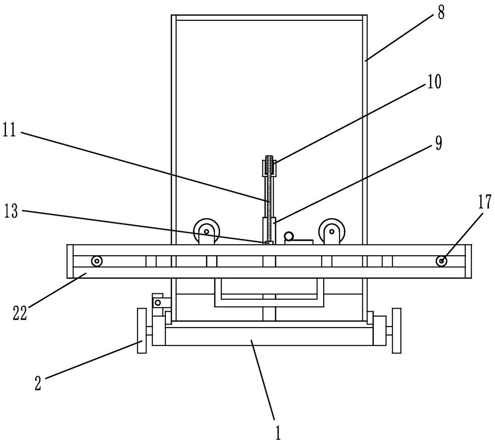
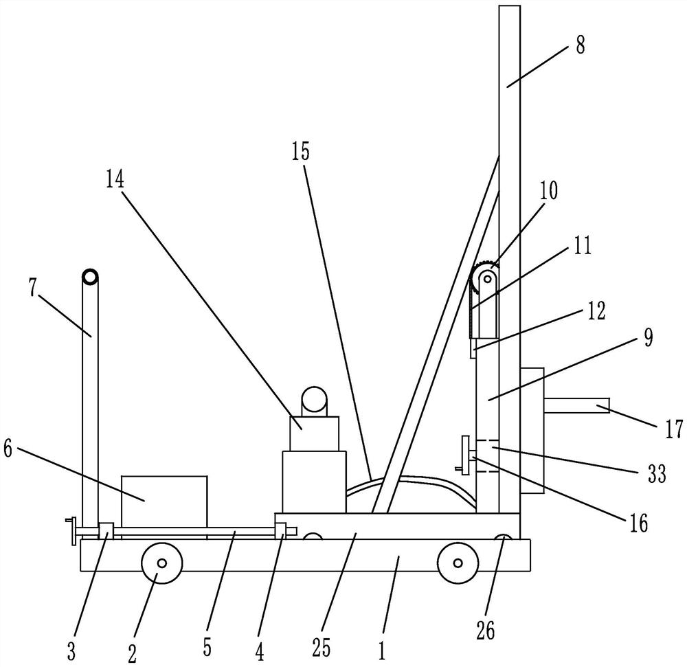
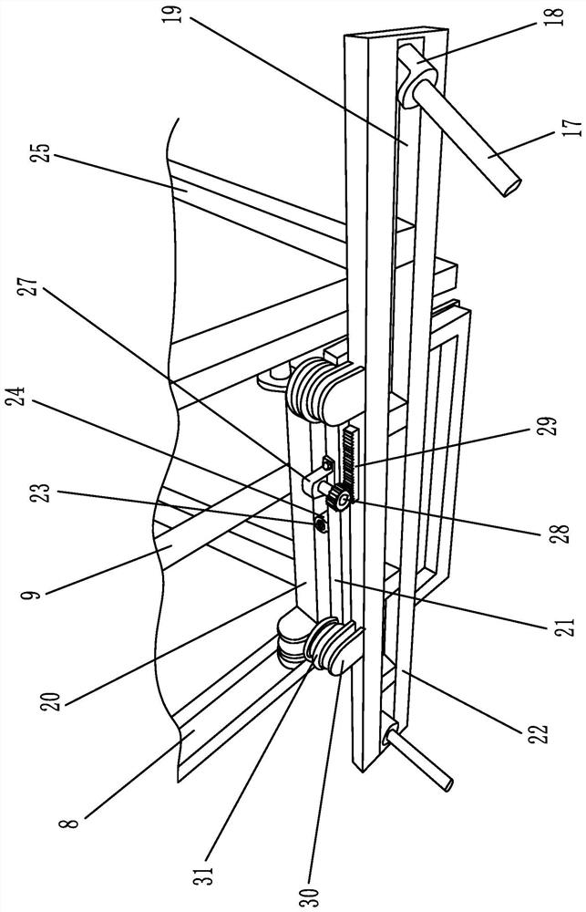
[0025] Embodiment 1: as figure 1 , 2 , shown in 3, a kind of assembling wall mobile assembly frame, comprises pulley 1, support device, the lifting mechanism that is used to drive the adjustment frame up and down, the translation fine-tuning mechanism that is used to drive the adjustment frame horizontal translation, is used to drive the adjustment frame vertical A flip adjustment mechanism for straight flipping and a feed adjustment mechanism for driving the sliding base to feed on the tackle. A track for sliding the support device is provided on the tackle, a wheel 2 and a motor 6 for driving the wheel are provided on the tackle, and a push rod 7 for pushing the tackle is provided at one end of the tackle away from the support device. The supporting device includes a sliding base 25 that is slidably connected with the tackle and a support arranged on the sliding base. The support includes a stand 8 and an adjustment frame that slides up and down with the stand. The adjustme...
Embodiment 2
[0027] Embodiment 2: The structure of this embodiment is basically the same as that of Embodiment 1, the difference is that, as Figure 4 , 5As shown, a drive rod 36 is arranged parallel to the bottom of the push rod, one end of the drive rod runs through the inside of the adjustment box, an eccentric wheel 42 is arranged at the end of the drive rod close to the adjustment box, and an accommodation cavity for accommodating the eccentric wheel is arranged in the adjustment box. A drive gear 33 is set on the rod, and the drive gear is connected to the ejector rod through a sliding spline 34. A transmission gear 35 capable of meshing with the drive gear is set on the drive rod; a linkage bevel gear 40 is set on the drive rod, and the sliding base There are pulleys connected by the drive shaft on both sides of the drive shaft, and the drive shaft is provided with a linkage worm 38 that matches the linkage bevel gear and a cam 39 that can push the linkage bevel gear. Preload sprin...
PUM
 Abstract
Description
Claims
Application Information
 - R&D
- Intellectual Property
- Life Sciences
- Materials
- Tech Scout
- Unparalleled Data Quality
- Higher Quality Content
- 60% Fewer Hallucinations
Browse by: Latest US Patents, China's latest patents, Technical Efficacy Thesaurus, Application Domain, Technology Topic, Popular Technical Reports.
© 2025 PatSnap. All rights reserved.Legal|Privacy policy|Modern Slavery Act Transparency Statement|Sitemap|About US| Contact US: help@patsnap.com


