A hoop fan cooling system for a turbofan engine

A turbo fan, fan cooling technology, used in engine components, machines/engines, liquid fuel engines, etc., to solve problems such as engine accidents, combustion, and melting of composite materials

Active Publication Date: 2021-07-09
NANJING UNIV OF AERONAUTICS & ASTRONAUTICS
View PDF6 Cites 0 Cited by
  • Summary
  • Abstract
  • Description
  • Claims
  • Application Information

AI Technical Summary

Problems solved by technology

Therefore, when a large amount of heat is accumulated at the gap between the hoop and the casing due to blast heat, the composite material at the casing will melt or even burn, causing engine accidents

Method used


Image

  • A hoop fan cooling system for a turbofan engine

Examples


Embodiment Construction

[0021] Below in conjunction with accompanying drawing, technical scheme of the present invention is described in further detail:

[0022] This invention may be embodied in many different forms and should not be construed as limited to the embodiments set forth herein. Rather, these embodiments are provided so that this disclosure will be thorough and complete, and will fully convey the scope of the invention to those skilled in the art. In the drawings, components are exaggerated for clarity.

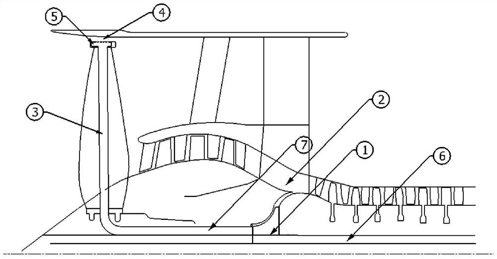
[0023] Aiming at the problem that the air blowing heat in the radial gap between the hoop fan hoop and the casing affects the safety of the engine, the present invention proposes a turbofan engine hoop fan cooling system, which includes a sleeve and a centrifugal compressor;

[0024] The hoop fan includes a main shaft, a hub, several fan blades and a hoop, and the hub is fixed on the main shaft; the several fan blades are arranged evenly in the circumferential direction between the hub...


PUM


Abstract

The invention discloses a hoop fan cooling system for a turbofan engine, which comprises a sleeve and a centrifugal compressor. The present invention utilizes the miniature centrifugal compressor on the main shaft of the fan to extract air flow in the radial gap from hoops, fan blades and wheel hubs, and discharge it into the main flow path after the supercharging stage after being pressurized. The gap airflow sucked away can take away the heat, thereby avoiding the accumulation of frictional heat of the airflow gap between the casing and the high-speed moving hoop to form a high temperature.

Description

technical field [0001] The invention relates to the field of aeroengine design, in particular to a fan / compressor system in a turbofan engine, in particular to a hoop fan cooling system for a turbofan engine. Background technique [0002] For civil airliners and transport aircraft, turbofan engines with large bypass ratios are often used. However, for fans, the increase in blade length will lead to a decrease in strength, so on the premise of ensuring that the weight does not increase significantly, ensuring the strength of the fan is a problem that designers need to consider. In addition, during the operation of the turbofan engine, the stall at the tip of the blade is one of the factors that pose a major threat to the fan, which will cause the fan blade to vibrate and easily break the blade. [0003] An important reason for tip stall is the influence of tip leakage flow. Due to the relative motion between the blade and the engine case, the blade needs to leave a certain ...

Claims


Application Information

Patent Timeline
Patent Type & Authority Patents(China)
IPC IPC(8): F04D29/58F04D29/32F04D29/38F01D25/12
CPCF01D25/12F04D29/325F04D29/329F04D29/388F04D29/582F04D29/5893
Inventor 李传鹏邹如萍胡骏阮立群彭宁航陈斌
Owner NANJING UNIV OF AERONAUTICS & ASTRONAUTICS
Why Eureka
Try Eureka