Disinfection equipment for nursing

A technology for disinfection equipment and boxes, which is applied in the direction of disinfection, sanitary equipment for toilets, water supply devices, etc. It can solve the problems of easily damaged nursing appliances and incomplete disinfection, and achieve the effect of sufficient disinfection

Inactive Publication Date: 2020-12-11
孙蓉
View PDF9 Cites 3 Cited by
  • Summary
  • Abstract
  • Description
  • Claims
  • Application Information

AI Technical Summary

Problems solved by technology

[0004] The purpose of the present invention is to solve the shortcomings of incomplete disinfection

Method used


Image

  • Disinfection equipment for nursing
  • Disinfection equipment for nursing
  • Disinfection equipment for nursing

Examples


Example Embodiment

[0027] Example one

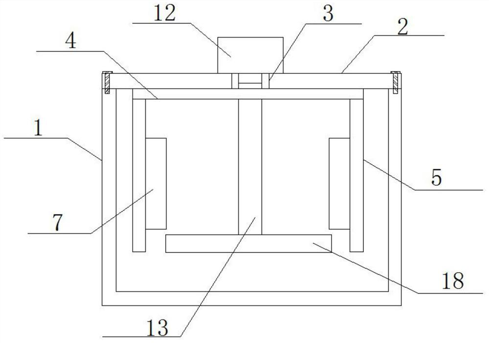
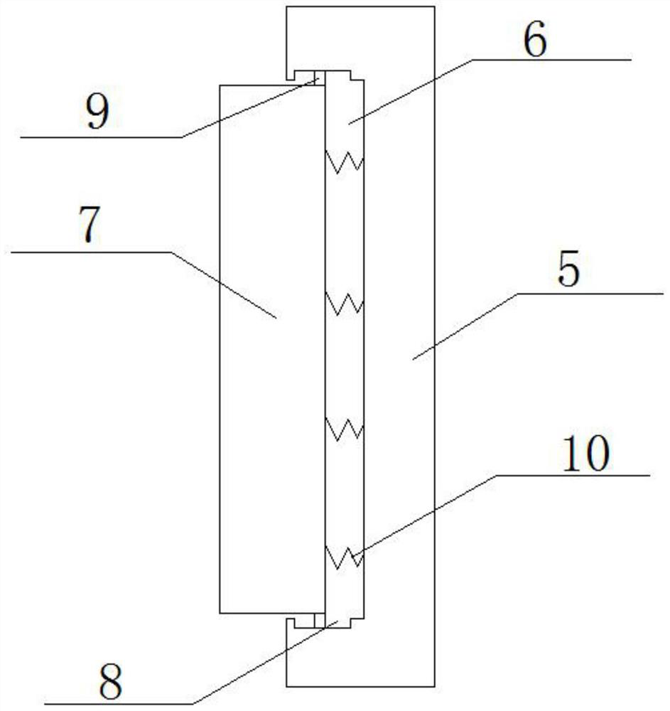
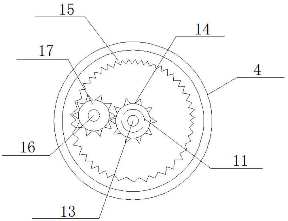
[0028] Refer Figure 1-7 The bottom one kind care disinfection apparatus, comprising a housing 1, the top case 1 is fixedly mounted by a bolt cover 2, and the top cover 2 is in the vertical direction defines a first aperture 3, the cover 2 rotatably mounted disc 4, and the interior of the hollow structure of the disc 4, the disc 4 is attached to the top are fixed two vertical rods 5, 5 a side close to each other are two vertical rods 6 defines a first recess, a first recess 6 and slides 7 attached to disinfect the brush, two side disinfecting brush 7 extends close to each other to the vertical bar 5, the upper inner wall of the top and bottom sides of the disc 4 are holes defined in the second 11, the top cover 2 is attached to the motor 12 is fixed, and the output shaft of the motor 12 is fixedly mounted at one end 13 of the rotatable lever, the other end of the rotating lever 13 sequentially through the first apertures and two second apertures 11 3 and extend...

Example Embodiment

[0036] Example 2

[0037] Refer Figure 1-7The bottom one kind care disinfection apparatus, comprising a housing 1, the top case 1 is fixedly mounted by a bolt cover 2, and the top cover 2 is in the vertical direction defines a first aperture 3, the cover 2 rotatably mounted disc 4, and the interior of the hollow structure of the disc 4, the disc 4 is attached to the top are fixed two vertical rods 5, 5 a side close to each other are two vertical rods 6 defines a first recess, a first recess 6 and slides 7 attached to disinfect the brush, two side disinfecting brush 7 extends close to each other to the vertical bar 5, the upper inner wall of the top and bottom sides of the disc 4 are holes defined in the second 11, the top cover 2 is attached to the motor 12 is fixed, and the output shaft of the motor 12 is fixedly mounted at one end 13 of the rotatable lever, the other end of the rotating lever 13 sequentially through the first apertures and two second apertures 11 3 and extends i...

Example Embodiment

[0045] Example three

[0046] Refer Figure 1-7 The bottom one kind care disinfection apparatus, comprising a housing 1, the top case 1 is fixedly mounted by a bolt cover 2, and the top cover 2 is in the vertical direction defines a first aperture 3, the cover 2 rotatably mounted disc 4, and the interior of the hollow structure of the disc 4, the disc 4 is attached to the top are fixed two vertical rods 5, 5 a side close to each other are two vertical rods 6 defines a first recess, a first recess 6 and slides 7 attached to disinfect the brush, two side disinfecting brush 7 extends close to each other to the vertical bar 5, the upper inner wall of the top and bottom sides of the disc 4 are holes defined in the second 11, the top cover 2 is attached to the motor 12 is fixed, and the output shaft of the motor 12 is fixedly mounted at one end 13 of the rotatable lever, the other end of the rotating lever 13 sequentially through the first apertures and two second apertures 11 3 and exte...


PUM


Abstract

The invention belongs to the technical field of disinfection, particularly relates to disinfection equipment for nursing, and provides the following scheme for solving the existing problems. The disinfection equipment comprises a box body, wherein a box cover is fixedly mounted at the top of the box body through bolts, a first small hole is formed in the top of the box cover in the vertical direction, and a disc is rotatably mounted at the bottom of the box cover; and the inner part of the disc is of a hollow structure, two vertical rods are fixedly mounted at the top of the disc, first grooves are formed in one sides close to each other, of the two vertical rods, disinfection brushes are mounted in the first grooves in a sliding mode, and one sides close to each other, of the two disinfection brushes extend out of the vertical rods. According to the disinfection equipment, the defects that in the prior art, disinfection is not thorough, and nursing tools are easy to damage are overcome, the nursing tools are prevented from being collided and damaged in the disinfection process by clamping the nursing tools, and sufficient disinfection is achieved by enabling the disinfection brushes and a containing disc to rotate in opposite directions.

Description

Technical field [0001] The present invention relates to the field of sterilization technique, particularly to a sterilizing treatment apparatus. Background technique [0002] Operating room space exists droplets and dust, can often pathogens. In order to prevent surgery when the patient unnecessary infections, surgical care must be possible for some utensils regularly disinfected. [0003] To this end measures are generally taken care appliances are placed into the surgical disinfection cleaning tank disinfection cleaning, but at the time of care appliances to clean, care appliances damaged often collide with each other, and sterilization is not complete, for this purpose to design a care disinfection equipment, not only make more thorough disinfection, and care appliances do not collide with each other. Inventive content [0004] Object of the present invention is to solve the prior art that sterilization is not complete and easily damaged care implement drawbacks, and one kind...

Claims


Application Information

Patent Timeline
IPC IPC(8): A61L2/18A61L2/26
CPCA61L2/18A61L2/26A61L2202/24
Inventor 孙蓉
Owner 孙蓉
Why Eureka
Try Eureka