Rotary pipe welding machine

A pipe welding machine, rotary technology, applied in the direction of welding equipment, tubular objects, welding accessories, etc., can solve the problems of insufficient welding precision and low welding efficiency, so as to improve welding efficiency, increase welding efficiency and welding precision, and increase fixing efficiency Effect

Inactive Publication Date: 2020-12-11
东阳市菊苏科技有限公司
View PDF13 Cites 8 Cited by
  • Summary
  • Abstract
  • Description
  • Claims
  • Application Information

AI Technical Summary

Problems solved by technology

[0005] In order to make up for the deficiencies of the existing technology and solve the problem of welding the larger-diameter round pipes in the prior art, a suspended welding machine is used to drive the welding torch to continuously rotate along the groove of the round pipe, and then to connect the two round pipes. Welding at the groove position, but the existing technology requires complex fixing devices to fix the welding platform to the pipe, the welding efficiency is low, and the welding accuracy is insufficient. The invention proposes a rotary pipe welding machine

Method used


Image

  • Rotary pipe welding machine
  • Rotary pipe welding machine
  • Rotary pipe welding machine

Examples


Embodiment approach

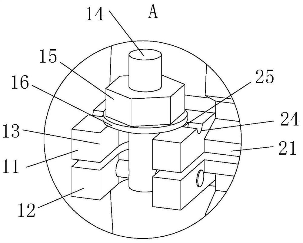
[0026]As an embodiment of the present invention, the top of the No. 1 splint 11 is provided with an arc-shaped groove 24, and the bottom of the gasket 16 is fixedly connected with an arc-shaped block 25 at the corresponding position of the arc-shaped groove 24, and the arc-shaped block 25 and the arc-shaped groove 24 cooperate with each other; the arc-shaped block 25 is snapped into the arc-shaped groove 24, and then the nut 15 is used to lock the gasket 16 and the snap ring 1, so that the arc-shaped block 25 presses the arc-shaped groove 24, thereby reducing the stud 14 The loosening of the vibration increases the firmness of the fixation between the snap ring 1 and the round pipe, and further reduces the adverse effect of the snap ring 1 loosening on the welding accuracy of the round pipe.

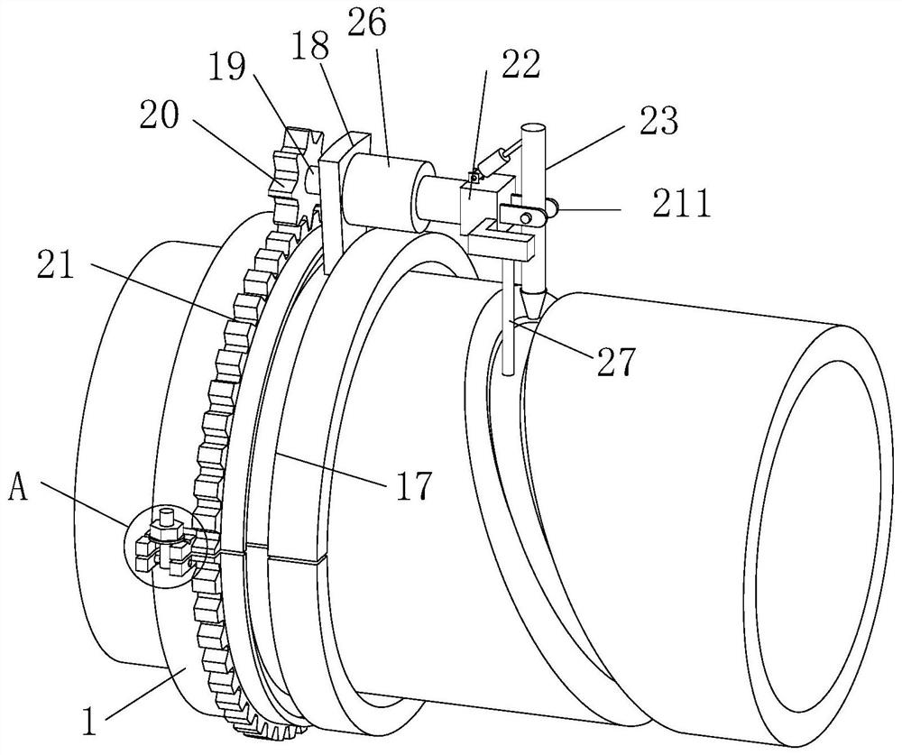
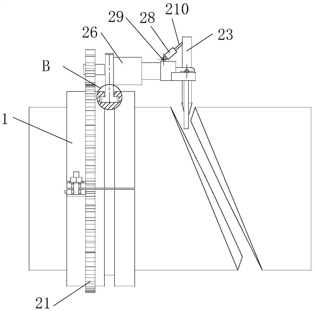
[0027] As an embodiment of the present invention, a telescopic rod 26 is fixedly connected between the soldering platform 22 and the T-shaped block 18; one side of the soldering platform ...


PUM


Abstract

The invention belongs to the technical field of welding machines, and particularly relates to a rotary pipe welding machine which comprises two semicircular clamping rings. The adjacent ends of one sides of the two clamping rings are hinged to each other, a first clamping plate and a second clamping plate are arranged at the ends of the other sides of the two clamping rings respectively, and U-shaped grooves are formed in the first clamping plate and the second clamping plate; a stud is hinged into the U-shaped groove of the first clamping plate through a rotating pin, the end, away from the rotating pin, of the stud is in threaded connection with a nut, and the part, between the nut and the rotating pin, of the stud is sleeved with a gasket; and an annular sliding groove is formed in theperipheries of the clamping rings, a T-shaped block is slidably connected into the sliding groove, a welding table is arranged at one side of the T-shaped block, and a welding gun is installed on thewelding table. According to the rotary pipe welding machine, the two semicircular clamping rings are opened and then clamped into the periphery of a round pipe, the stud is clamped into the U-shaped groove in the first clamping plate, and then the two clamping rings are quickly locked in cooperation with the nut and the gasket, so that the welding efficiency and the welding precision of the welding machine on the round pipe are improved.

Description

technical field [0001] The invention belongs to the technical field of welding machines, in particular to a rotary pipe welding machine. Background technique [0002] The suspended automatic tube-sheet argon arc welding machine is a special welding machine used for welding the joints of heat exchange tubes and tube sheets of large heat exchangers. When welding, the torch of the welding machine needs to rotate around the heat exchange tube to be welded to complete the welding of the 360° annular weld. Moreover, during welding, the higher welding temperature will cause slight deformation of the welded pipe fittings, which will affect the welding quality. [0003] There are also some technical solutions about welding machines in the prior art. For example, a Chinese patent with application number 2011203921039 discloses a suspended automatic tube-sheet argon arc welding machine quick positioning device, including a welding machine, a tube-sheet and a For welding pipe fittings...

Claims


Application Information

Patent Timeline
Patent Type & Authority Applications(China)
IPC IPC(8): B23K9/00B23K9/32
CPCB23K9/00B23K9/32B23K2101/06
Inventor 章奕英
Owner 东阳市菊苏科技有限公司
Why Eureka
Try Eureka