
Motor fault detection device

A technology for fault detection and troubleshooting, which is applied to measuring devices, devices using electric/magnetic methods, speed/acceleration/shock measurement, etc. It can solve the problems of inability, connection, and inconvenient use of the socket to achieve fixed and stable Effect

Inactive Publication Date: 2020-12-11
曹亮
View PDF1 Cites 1 Cited by
  • Summary
  • Abstract
  • Description
  • Claims
  • Application Information

AI Technical Summary

Problems solved by technology

[0003] But this device is only applicable to the situation that the motor is in the car body. When detecting the fault of the motor that has just left the factory, the plug-in part of the device cannot be connected with the output shaft of the motor, which is not convenient for use.

Method used


Image

  • Motor fault detection device
  • Motor fault detection device
  • Motor fault detection device

Examples


Embodiment Construction

[0024] The following will clearly and completely describe the technical solutions in the embodiments of the present invention with reference to the accompanying drawings in the embodiments of the present invention. Obviously, the described embodiments are only some, not all, embodiments of the present invention. Based on the embodiments of the present invention, all other embodiments obtained by persons of ordinary skill in the art without creative efforts fall within the protection scope of the present invention.

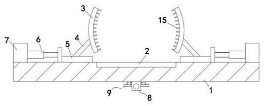
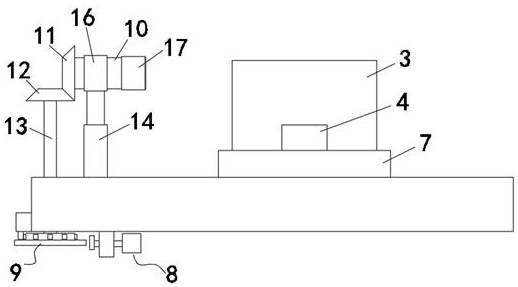
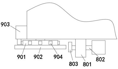
[0025] see Figure 1-4 , the present invention provides a technical solution: a motor fault detection device, including a fault repair station 1, a motor placement slot 2 is provided in the middle of the top surface of the fault repair station 1, and a motor fixing plate is provided on the left and right sides of the motor placement slot 2 3. The motor fixing plate 3 is in an arc shape matching the shape of the motor body. The outer side of the motor fixing plate 3...


PUM


Abstract

The invention relates to the technical field of motor detection, in particular to a motor fault detection device which comprises a fault maintenance platform. A motor placing groove is formed in the middle of the top surface of the fault maintenance platform. Motor fixing plates are arranged on the left side and the right side of the motor placing groove. A vertical second electric push rod is arranged on the rear side of a fixing block. A horizontal rotating shaft is arranged at the top of the second electric push rod. A first bevel gear is fixed to the left side of the rotating shaft. A second bevel gear is meshed with the bottom of the first bevel gear. A rotating connecting rod is fixed to the bottom of the second bevel gear, and a rotating speed detection assembly is connected to thebottom end of the rotating connecting rod. The motor fixing plates and the motor placing groove are arranged, the motor placing groove can stably fix a flange piece at the bottom of a motor body, thefront side and the rear side of the motor body can be clamped through the motor fixing plates, fixing teeth on the motor fixing plates are embedded between fins on the motor body, and fixing is more stable.

Description

technical field [0001] The invention relates to the technical field of motor detection, in particular to a motor fault detection device. Background technique [0002] Existing motors such as Figure 4 As shown, it is usually necessary to use a fault detection device to detect it. For example, Patent No. CN201920237360.1 discloses a motor fault detection device, which includes a support part. The upper part of the support part is rotated with a first rotating shaft, and one end of the first rotating shaft is provided with a turntable. The other end of the first rotating shaft is provided with a first pulley, a magnet is provided on the side of the first pulley away from the support part, a mounting part is provided on the side of the support part away from the turntable, and a coil and a warning are provided on the mounting part. The light, warning light and coil are electrically connected, and the coil is located inside the magnet. The invention not only has the characteri...

Claims


Application Information

Patent Timeline
Patent Type & Authority Applications(China)
IPC IPC(8): G01P3/44G01P1/00
CPCG01P1/00G01P3/44
Inventor 曹亮
Owner 曹亮
Learn More