Industrial sewage collecting tank

A technology for industrial sewage and collection pools, applied in water/sewage treatment, water/sludge/sewage treatment, water supply equipment, etc., can solve the problems of prolonging the time of sewage discharge and low efficiency, and prevent debris from running around, The effect of improving efficiency

Inactive Publication Date: 2020-12-15
彭川
View PDF0 Cites 3 Cited by
  • Summary
  • Abstract
  • Description
  • Claims
  • Application Information

AI Technical Summary

Problems solved by technology

[0003] When collecting industrial sewage, it is necessary to salvage the sundries in the sewage to facilitate subsequent treatment. The existing salvage equipment for industrial sewage garbage needs to intermittently stop the discharge of sewage during use, and the stop time is used to process the salvage. debris, which is convenient for the next salvage, but the efficiency of this salvage method is too low, and it prolongs the time of sewage discharge

Method used


Image

  • Industrial sewage collecting tank
  • Industrial sewage collecting tank
  • Industrial sewage collecting tank

Examples


Embodiment 1

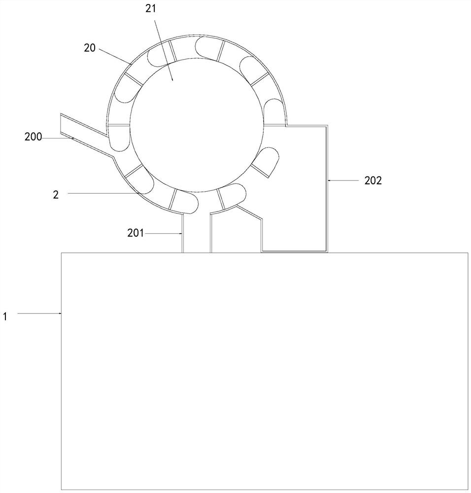
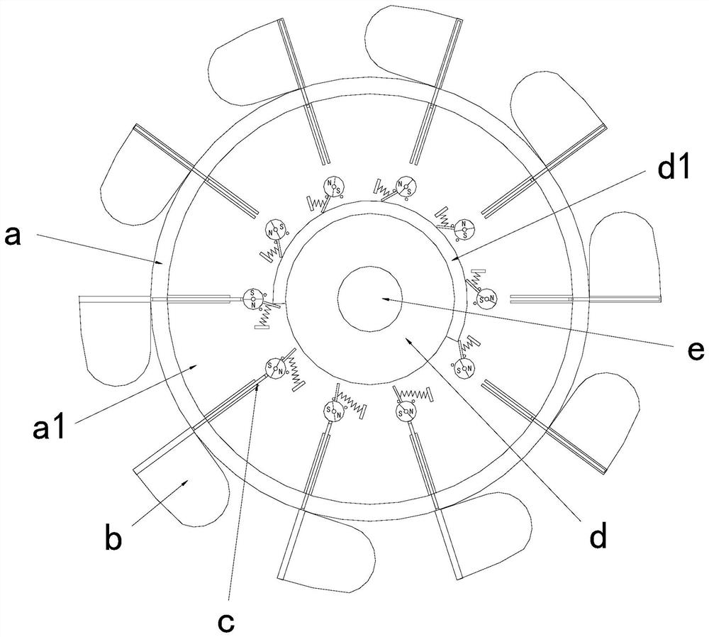
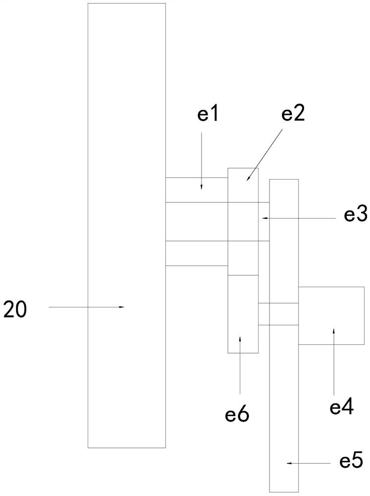
[0026] see Figure 1-2 , the present invention provides a technical solution for industrial sewage collection ponds: its structure includes a collection pond 1 and a salvage structure 2, a salvage structure 2 is arranged above the collection pond 1, and the salvage structure 2 includes a shell 20, a rotary fisher 21 , the housing 20 is provided with a rotary fisher 21, the side of the housing 20 is provided with a water inlet 200, the bottom of the housing 20 is provided with a water outlet 201, and the housing 20 is provided with the opposite of the water inlet 200 The side is connected with a collection tank 202, and the rotary fisher 21 includes a turntable a, a fishing net b, an upper cover structure c, a fixed disk d, and a power structure e, and the side of the turntable a is connected with evenly distributed fishing nets b. A cavity a1 is provided inside the turntable a, and a fixed disk d is arranged in the middle of the cavity a1. The upper cover structure c is evenly...

Embodiment 2

[0029] see Figure 1-4 , the present invention provides a technical solution for industrial sewage collection ponds: its structure includes a collection pond 1 and a salvage structure 2, a salvage structure 2 is arranged above the collection pond 1, and the salvage structure 2 includes a shell 20, a rotary fisher 21 , the housing 20 is provided with a rotary fisher 21, the side of the housing 20 is provided with a water inlet 200, the bottom of the housing 20 is provided with a water outlet 201, and the housing 20 is provided with the opposite of the water inlet 200 The side is connected with a collection tank 202, and the rotary fisher 21 includes a turntable a, a fishing net b, an upper cover structure c, a fixed disk d, and a power structure e, and the side of the turntable a is connected with evenly distributed fishing nets b. There is a cavity a1 inside the turntable a, and a fixed disk d is arranged in the middle of the cavity a1. The upper cover structure c is evenly di...


PUM


Abstract

The invention discloses an industrial sewage collecting tank which structurally comprises a collecting tank and a fishing structure, the fishing structure is arranged above the collecting tank, the fishing structure comprises a shell and a rotary fisher, the rotary fisher is arranged in the shell, a water inlet is formed in the side face of the shell, a water outlet is formed in the bottom of theshell, and a collecting tank is connected to the side, opposite to the side provided with the water inlet, of the shell; The rotary fisher comprises a rotary disc, a fishing net, an upper cover structure, a fixed disc and a power structure, the evenly-distributed fishing net is connected to the side face of the rotary disc, a cavity is formed in the rotary disc, and the fixed disc is arranged in the middle of the cavity. The invention has the beneficial effects that impurities in industrial sewage can be continuously fished through the continuously rotating fishing net, so that the tank can continuously work, and the feeding of waste water does not need to be stopped; therefore, the sewage treatment efficiency is improved, the fishing net can be opened and closed in time through the uppercover structure, and sundries are prevented from being attached to the back face of the next fishing net in a disordered mode.

Description

technical field [0001] The invention relates to the field of sewage treatment, in particular to an industrial sewage collection pool. Background technique [0002] The random discharge of industrial sewage will cause pollution, and it is necessary to collect and treat industrial sewage to prevent pollution to the environment. [0003] When collecting industrial sewage, it is necessary to salvage the sundries in the sewage to facilitate subsequent treatment. The existing salvage equipment for industrial sewage garbage needs to intermittently stop the discharge of sewage during use, and the stop time is used to process the salvage. The debris is convenient for the next salvage, but the efficiency of this salvage method is too low, and it prolongs the time for sewage discharge. Contents of the invention [0004] The main purpose of the present invention is to overcome the deficiencies in the prior art and provide a kind of industrial sewage collection tank. [0005] The pre...

Claims


Application Information

Patent Timeline
Patent Type & Authority Applications(China)
IPC IPC(8): B01D33/333B01D33/76B01D33/80E03F5/10E03F5/14E03F5/26
CPCB01D33/333B01D33/76B01D33/801B01D33/802E03F5/10E03F5/14E03F5/26
Inventor 彭川
Owner 彭川
Why Eureka
Try Eureka