Ultrasonic transducer

A transducer and ultrasonic technology, applied in the direction of fluid using vibration, etc., can solve the problems of low sound intensity and unsatisfactory cleaning effect, and achieve the effect of increasing the aesthetic feeling and improving the sound intensity

Pending Publication Date: 2020-12-15
SUZHOU JIAHUI ULTRASONIC TECH CO LTD
View PDF0 Cites 0 Cited by
  • Summary
  • Abstract
  • Description
  • Claims
  • Application Information

AI Technical Summary

Problems solved by technology

[0003] The technical problem to be solved by the present invention is to provide an ultrasonic transducer, which is used to solve the technical problems of low sound intensity and unsatisfactory cleaning effect of the ultrasonic transducer in the prior art

Method used


Image

  • Ultrasonic transducer
  • Ultrasonic transducer
  • Ultrasonic transducer

Examples


Embodiment 1

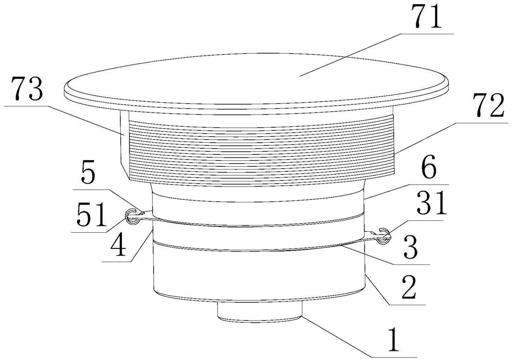
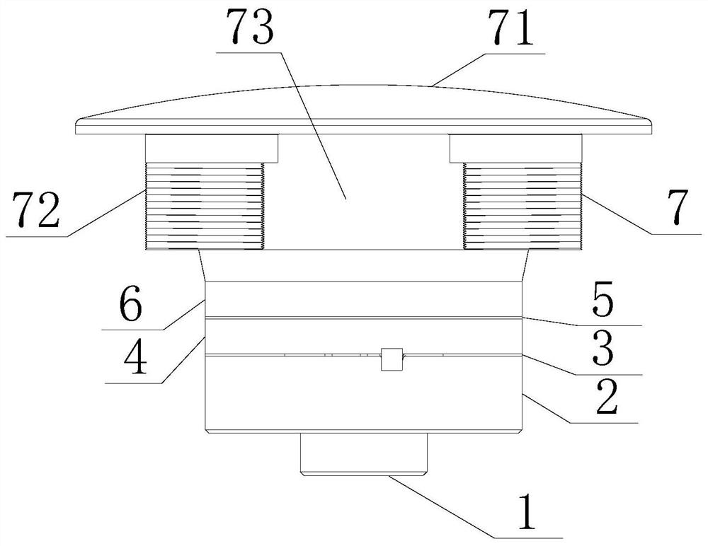
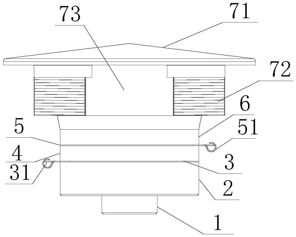
[0026] figure 1 and figure 2 The ultrasonic transducer shown, comprising a lower cap 2 is provided from bottom to top, the first electrode sheet 3, 4 of the first piezoelectric ceramic, the second electrode sheet 5, 6 and second piezoelectric ceramic cover. Lower cap 2, the first electrode sheet 3, 4 of the first piezoelectric ceramic, the second electrode sheet 5, 6 and second piezoelectric ceramic cover from the bottom up through the axis is provided through a locking bolt secured. The top cover is welded or fixed to the cap 7 by glue bonding, the upper end surface of the oscillation 71 is a spherical cap 7. The lower end cap 7 is provided with the connecting portion, the connecting portion is a hollow cylindrical structure, connected to the upper cover portion sleeved on the outer side, is provided with two threaded connecting portions of the outer wall surface 72 and two flat facets 73, 72 and two flanks two flat facets 73 are alternately disposed, and radially symmetrical, t...

Embodiment 2

[0028] like image 3 and Figure 4 , The present embodiment is substantially same as a configuration embodiment, except that 71 different shapes of the oscillation plane thereof, which oscillation surface 71 is a tapered surface.


PUM

PropertyMeasurementUnit
Diameteraaaaaaaaaa
Thicknessaaaaaaaaaa
Heightaaaaaaaaaa

Abstract

The invention discloses an ultrasonic transducer. The ultrasonic transducer comprises a lower cover, a first electrode plate, first piezoelectric ceramic, a second electrode plate, second piezoelectric ceramic and an upper cover which are sequentially arranged from bottom to top, wherein the lower cover, the first electrode plate, the first piezoelectric ceramic, the second electrode plate, the second piezoelectric ceramic and the upper cover are locked and fixed through bolts penetrating through the axis from bottom to top, the ultrasonic transducer is characterized in that a cover cap is fixedly installed at the top of the upper cover, the upper end face of the cover cap is a vibration generating face, and the vibration generating face is a protruding face gradually protruding upwards from the edge to the center or an arc face protruding towards the middle from the two sides. According to the ultrasonic transducer, the structure of a traditional ultrasonic transducer is adjusted, thevibration generating face of the ultrasonic transducer is changed from a plane to a convex surface with a certain height, and the sound intensity of the ultrasonic transducer is improved.

Description

Technical field [0001] The present invention relates to an ultrasonic transducer TECHNICAL FIELD particular to a surface oscillation is arcuate or tapered ultrasonic transducer. Background technique [0002] Currently, the ultrasound transducer is mainly used for cleaning, and in particular that the ultrasonic transducer is mounted at the bottom of the tank, and the tank is close to the oscillation plane, away from the other parts of the tank. In this process, an ultrasonic transducer under the control of the ultrasonic generator, the electrical energy into mechanical energy and then emit ultrasound, high frequency ultrasonic waves to vibrate a liquid medium compression, so that the liquid molecules generated alternating positive and negative shock wave. When the ultrasonic sound intensity reaches a certain value, the liquid fine cavitation bubbles grow abruptly and instantaneously strongly closed, a strong micro-explosion shock wave and the surface to be cleaned of dirt destruct...

Claims


Application Information

Patent Timeline
IPC IPC(8): B06B1/06
CPCB06B1/0633
Inventor 赵锦成
Owner SUZHOU JIAHUI ULTRASONIC TECH CO LTD
Why Eureka
Try Eureka