Supercharge Your Innovation With Domain-Expert AI Agents!

A high-speed and high-power coupling shaft reducer

A high-power, reducer technology, applied in the direction of transmission, gear lubrication/cooling, gear transmission, etc., can solve the bottleneck of the overall quality of life improvement, large dynamic load, can not meet the limit requirements and other problems

Active Publication Date: 2021-09-10
李雪琴
View PDF1 Cites 0 Cited by
  • Summary
  • Abstract
  • Description
  • Claims
  • Application Information

AI Technical Summary

Problems solved by technology

[0004] In the construction of shale gas development projects, mechanical reciprocating energy conversion equipment is commonly used, but when its power reaches a certain level, it can no longer meet the restriction requirements of engineering construction; at this time, mechanical rotating turbofan energy conversion equipment has become a more It is an excellent choice, because of the continuity of its energy conversion, its advantages in mobile equipment have begun to fully manifest, such as Russian turbofan engine tanks and American littoral combat ships. Advantage
[0005] With the breakthrough of my country's aircraft engine technology and the realization of C919 integrated innovation, the expanded application field of turbofan engine will have a greater development; therefore, higher requirements are also put forward for the reducer in the transmission process, application number 201610919639.9 is a high-speed and high-power coaxial reducer. Due to the large dynamic load carried by its high-speed planetary gear assembly, it is difficult to meet the long-term use requirements of the existing high-speed and high-precision rolling bearings. The life of the rolling bearings in the planetary gear assembly It has become a bottleneck restricting the overall quality improvement of products

Method used


Image

  • A high-speed and high-power coupling shaft reducer
  • A high-speed and high-power coupling shaft reducer
  • A high-speed and high-power coupling shaft reducer

Examples


Embodiment Construction

[0027] Embodiments of the technical solutions of the present invention will be described in detail below in conjunction with the accompanying drawings. The following examples are only used to illustrate the technical solutions of the present invention more clearly, and therefore are only examples, rather than limiting the protection scope of the present invention.

[0028] It should be noted that, unless otherwise specified, the technical terms or scientific terms used in this application shall have the usual meanings understood by those skilled in the art to which the present invention belongs.

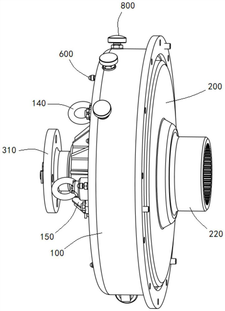
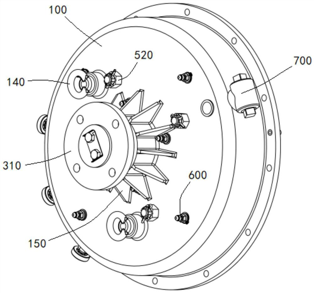
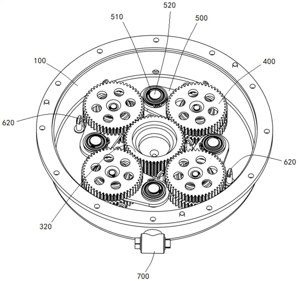
[0029] Such as Figure 1-8 As shown, this embodiment provides a high-speed and high-power shaft-coupled reducer, including: a housing 100, one end of the housing 100 is open, and the outer side of the housing 100 is rotated away from the central position of the opening to provide an input end , the input end is provided with a sun gear 320 corresponding to the part inside the housin...


PUM


Abstract

The invention discloses a high-speed and high-power coupling reducer, comprising: a housing, one end of the housing is open, and an input end is arranged on the back and outer side of the housing to rotate away from the central position of the opening, and the input end corresponds to A part of the casing is provided with a sun gear, and a plurality of planetary gear assemblies are arranged symmetrically corresponding to the sun gear in the casing, and a rotating disk is arranged at the opening of the casing, and a rotating disk is arranged on the edge of the rotating disk. The inner ring gear that is meshed with the planetary gear, the center of the side of the rotating disk away from the housing is extended outwards, and an output end coaxially arranged with the input end is provided, and the planetary gear assembly and the inner ring gear can be arranged Two-stage deceleration is formed, so that the rotating disk can decelerate and output power. The planetary gear is installed in the casing through the cantilever assembly. The long run of the gears.

Description

technical field [0001] The invention relates to the technical field of reducers, in particular to a high-speed and high-power shaft-coupled reducer. Background technique [0002] With the continuous increase of power demand for field engineering construction, the requirements for the floor area and weight restrictions of construction and transportable equipment are also increasing. [0003] The economical requirements of the project require that the construction site occupy a small area, and the equipment going to the site for construction must meet the conditions for land transportation under pressure. [0004] In the construction of shale gas development projects, mechanical reciprocating energy conversion equipment is commonly used, but when its power reaches a certain level, it can no longer meet the restriction requirements of engineering construction; at this time, mechanical rotating turbofan energy conversion equipment has become a more It is an excellent choice. Du...

Claims


Application Information

Patent Timeline
Patent Type & Authority Patents(China)
IPC IPC(8): F16H1/32F16H57/08F16H57/04F16H57/023F16H57/021F16H57/027
CPCF16H1/32F16H57/023F16H57/027F16H57/0421F16H57/0456F16H57/0479F16H57/08F16H2001/327F16H2057/085
Inventor 李雪琴
Owner 李雪琴
Features
  • R&D
  • Intellectual Property
  • Life Sciences
  • Materials
  • Tech Scout
  • Unparalleled Data Quality
  • Higher Quality Content
  • 60% Fewer Hallucinations
Learn More