High-precision laser measuring instrument

A laser measuring instrument, high-precision technology, applied in the field of measuring tools, can solve the problems of being easy to lose, unable to measure by a single person, unable to spare one hand with both hands, etc.

Inactive Publication Date: 2020-12-15
广州华赋知识产权咨询有限公司
View PDF0 Cites 0 Cited by
  • Summary
  • Abstract
  • Description
  • Claims
  • Application Information

AI Technical Summary

Problems solved by technology

[0003] The laser measuring instruments in the prior art are generally small in size. Although they are more convenient to carry, due to the lack of anti-lost structure, they are often easy to lose due to their small size in actual use, and the laser measuring instrument itself The price of the instrument is several times more expensive than that of ordinary measuring instruments. If it is lost, it will not only increase the cost but also cause the phenomenon that the site cannot be measured.
[0004] At the same time, when the existing laser measuring instrument is used in practice, due to its special structure, it is often made into a square box, that is, it is similar in shape and size to a traditional feature phone, but it still needs to be held in one hand during the actual measurement process. Take the laser measuring instrument, but sometimes encounter the phenomenon that both hands need to work and cannot spare one hand. At this time, it will cause the phenomenon that a single person cannot measure, which reduces the work efficiency

Method used


Image

  • High-precision laser measuring instrument
  • High-precision laser measuring instrument
  • High-precision laser measuring instrument

Examples


Embodiment Construction

[0057] The following will clearly and completely describe the technical solutions in the embodiments of the present invention with reference to the accompanying drawings in the embodiments of the present invention. Obviously, the described embodiments are only some, not all, embodiments of the present invention. Based on the embodiments of the present invention, all other embodiments obtained by persons of ordinary skill in the art without making creative efforts belong to the protection scope of the present invention.

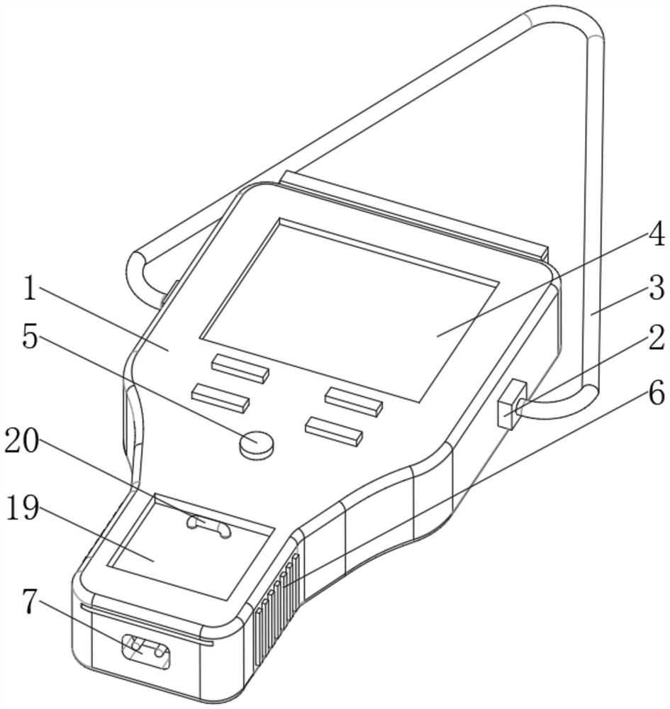
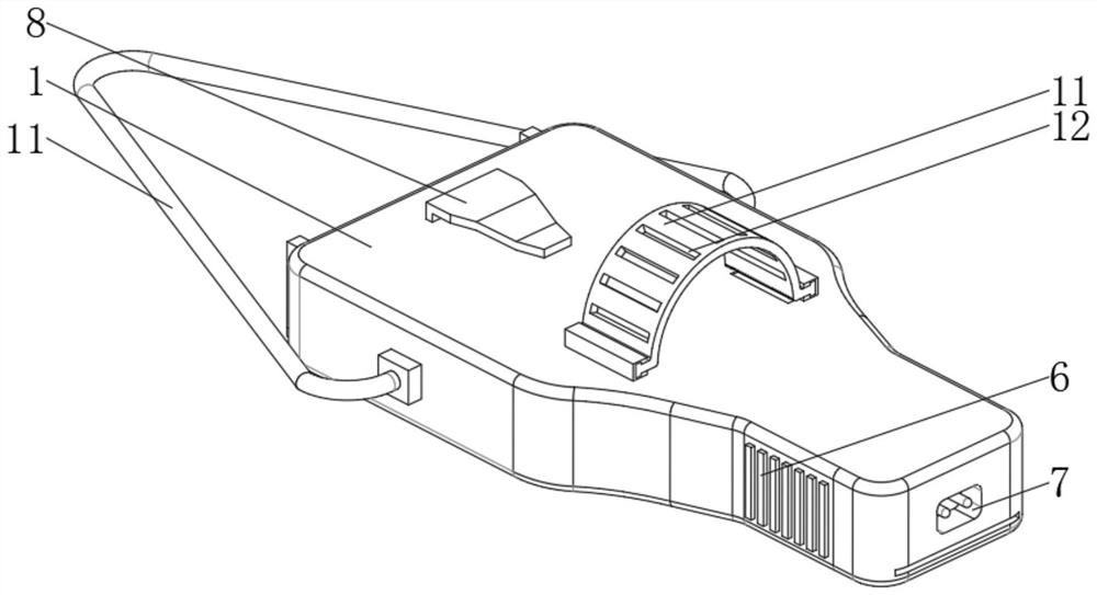
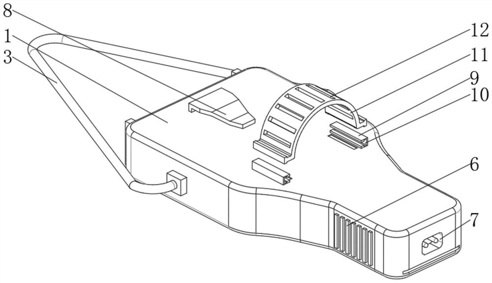
[0058] see Figure 1-6 , a high-precision laser measuring instrument, including a laser measuring instrument body 1, a fixed block 2 is fixedly installed at the left and right ends of the laser measuring instrument body 1, and a fixed block located above the laser measuring instrument body 1 is fixedly installed between the two fixed blocks 2 The lanyard 3 of the laser measuring instrument body 1 is fixedly installed with a back clip 8, the front of the laser ...


PUM


Abstract

The invention relates to the technical field of measuring tools, and discloses a high-precision laser measuring instrument. The high-precision laser measuring instrument comprises a laser measuring instrument body, wherein fixing blocks are fixedly installed at the left end and the right end of the laser measuring instrument body, and a hanging rope located above the laser measuring instrument body is fixedly installed between the two fixing blocks; a back clamp is fixedly installed on the upper portion of the back face of the laser measuring instrument body; and a touch screen is fixedly installed on the front face of the laser measuring instrument body. According to the high-precision laser measuring instrument, the fixing blocks are fixed to the left end and the right end of a laser measuring instrument body, the hanging rope located above the laser measuring instrument body is fixed between the two fixing blocks, the back clamp is fixed to the upper portion of the back face of thelaser measuring instrument body, and the laser measuring instrument body can be hung on a notebook computer or a pocket through the back clamp on the back. Meanwhile, the laser measuring instrument body can be hung on the neck through using the hanging rope, so as to be prevented from being lost due to the too small size, and therefore the high-precision laser measuring instrument has the advantage of having a certain anti-lost function.

Description

technical field [0001] The invention relates to the technical field of measuring tools, in particular to a high-precision laser measuring instrument. Background technique [0002] A laser measuring instrument generally refers to a laser rangefinder, which is an instrument that uses a certain parameter of a modulated laser to measure the distance of a target. The measuring range of the laser rangefinder is 3.5 to 5000 meters. According to the distance measuring method, it is divided into phase method range finder and pulse method range finder. The pulse laser range finder emits a beam or a series of short pulse laser beams to the target during operation, and the photoelectric element receives the laser reflected by the target. The timer measures the time from launch to reception of the laser beam, and calculates the distance from the observer to the target. The phase method laser rangefinder detects the distance by detecting the phase difference between the emitted light an...

Claims


Application Information

Patent Timeline
Patent Type & Authority Applications(China)
IPC IPC(8): G01S7/481G01S17/08G01R31/392G06F3/041
CPCG01S7/481G01S17/08G06F3/0412G01R31/392G06F3/04164
Inventor 叶景辉
Owner 广州华赋知识产权咨询有限公司
Why Eureka
Try Eureka