Drawing equipment used for birdcage
A wire drawing and equipment technology, applied in the field of birdcage wire drawing equipment, can solve problems such as slow wire drawing speed
- Summary
- Abstract
- Description
- Claims
- Application Information
AI Technical Summary
Problems solved by technology
Method used
Image
Examples
Embodiment 1
[0023]A wire drawing equipment for bird cages, such asfigure 1 As shown, it includes a base 1, a servo motor 2, a wire drawing mechanism 3, a wire drawing plate 4, an intermittent rotation mechanism 5, and a pushing mechanism 6. The upper front side of the base 1 is provided with a servo motor 2, and the upper right side of the base 1 is provided with a wire drawing mechanism 3. A drawing plate 4 is provided in the middle of the upper part of the base 1, an intermittent rotating mechanism 5 is provided on the left side of the upper part of the base 1, and a material pushing mechanism 6 is provided on the left side of the upper part of the base 1.
[0024]When the user needs a wooden pole for wire drawing in the process of making a birdcage, you can use this equipment. First, place the wooden pole that needs to be drawn on the intermittent rotating mechanism 5, and then start the servo motor 2 through the servo motor 2. Drive the wire drawing mechanism 3 to fix the wooden rod. The rotat...
Embodiment 2
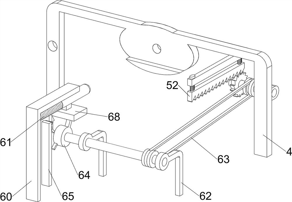
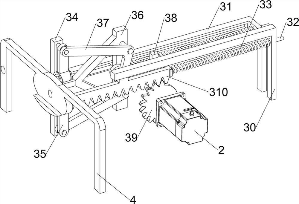
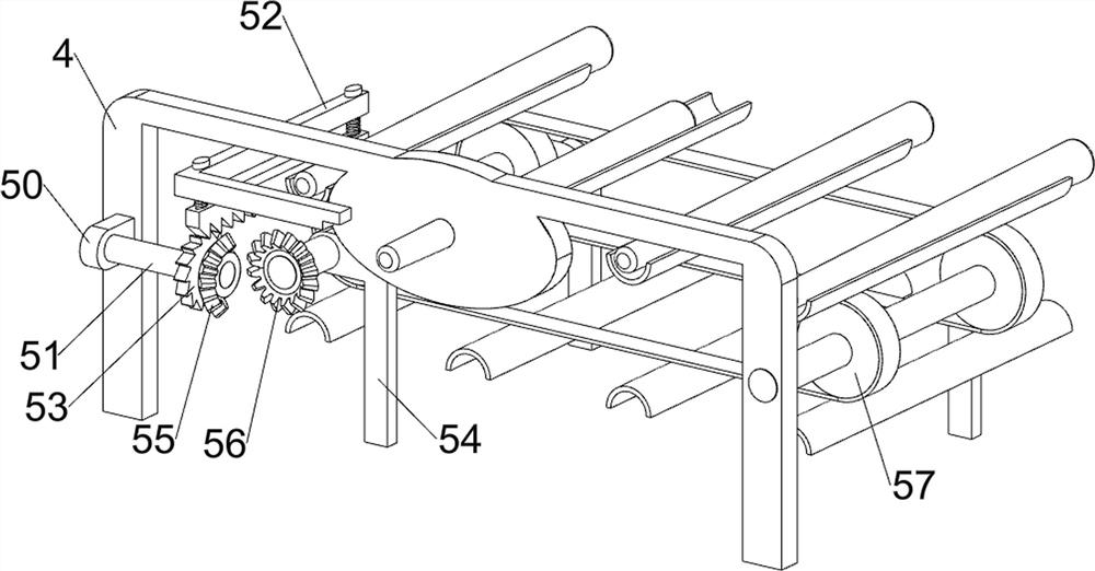
[0026]On the basis of Example 1, such asfigure 2 ,image 3 ,Figure 4 withFigure 5 As shown, the wire drawing mechanism 3 includes a first sliding rail 30, a second sliding rail 31, a first sliding rod 32, a first spring 33, a third sliding rail 34, a clamping block 35, a first fixing block 36, and a rotating handle 37. The connecting block 38, the first missing gear 39 and the first rack 310, the upper right front side of the base 1 is provided with a first slide rail 30, the upper right rear side of the base 1 is provided with a second slide rail 31, and the first slide rail 30 Connected with the second slide rail 31, the first slide rail 30 and the second slide rail 31 are slidably provided with a first slide rod 32, the first slide rod 32 is sleeved with a first spring 33, and the second slide rail 31 The upper sliding type is provided with a third sliding rail 34, the left side of the first sliding rod 32 on the rear side is connected with a first fixing block 36, the first fixin...
Embodiment 3
[0033]On the basis of Example 2, such asfigure 1 withFigure 6 As shown, it also includes a second sliding rod 7, a fixed frame 8 and a fourth spring 9. The upper middle of the drawing plate 4 is provided with a fixed frame 8, and the fixed frame 8 is slidably provided with a second sliding rod 7, the second sliding rod A fourth spring 9 is sleeved on 7 and the lower end of the fourth spring 9 is connected with the fixed frame 8.
[0034]After the wood rod is drawn, there will be wood shavings on the drawing board 4, so that the user can press the second sliding rod 7 downwards. At this time, the fourth spring 9 is compressed and the second sliding rod 7 moves downward. The shavings will not be blocked on the drawing board 4 when the shavings are pushed down, which is convenient for the subsequent wooden poles to draw on the drawing board 4. When the user no longer applies force to the second sliding rod 7, the action of the fourth spring 9 Under the force, the second sliding rod 7 mov...
PUM
 Abstract
Description
Claims
Application Information
 - R&D
- Intellectual Property
- Life Sciences
- Materials
- Tech Scout
- Unparalleled Data Quality
- Higher Quality Content
- 60% Fewer Hallucinations
Browse by: Latest US Patents, China's latest patents, Technical Efficacy Thesaurus, Application Domain, Technology Topic, Popular Technical Reports.
© 2025 PatSnap. All rights reserved.Legal|Privacy policy|Modern Slavery Act Transparency Statement|Sitemap|About US| Contact US: help@patsnap.com


