Rapid cement bag breaking equipment for construction site

A construction site and bag breaking technology, which is applied in the field of cement rapid bag breaking equipment on construction sites, can solve problems such as troublesome operation, low work efficiency, and dust affecting the surrounding environment, and achieve the effect of not being easily injured

Active Publication Date: 2020-12-18
山东未来城建筑工程有限公司
View PDF5 Cites 4 Cited by
  • Summary
  • Abstract
  • Description
  • Claims
  • Application Information

AI Technical Summary

Problems solved by technology

[0003] At present, most of the cement bags are broken manually. First, the cement is pulled to the use site with a hook, and then the cement bag is broken with a knife, and then the cement bag is lifted to pour the cement out. This operation is more troublesome and the work efficiency is lower. It is still low, and when the cement is broken, the cement is easy to raise dust and affect the surrounding environment, and also cause damage to people's physical and mental health.

Method used


Image

  • Rapid cement bag breaking equipment for construction site
  • Rapid cement bag breaking equipment for construction site
  • Rapid cement bag breaking equipment for construction site

Examples


Embodiment 1

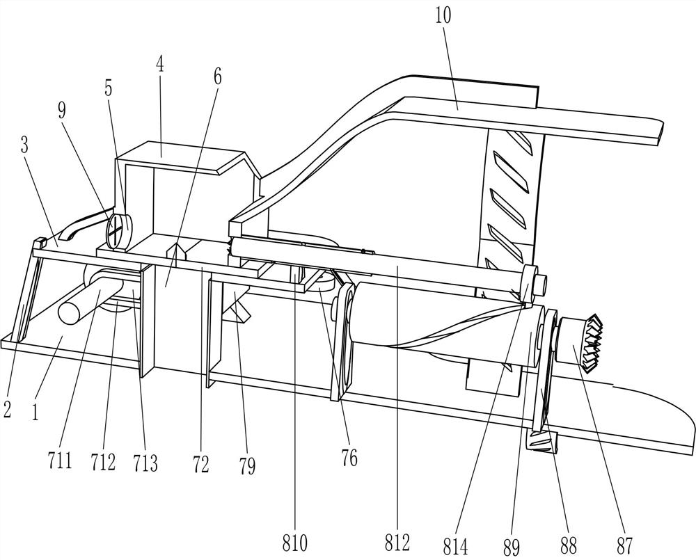
[0024] A kind of construction site cement quick breaking bag equipment, such as figure 1 , figure 2 , image 3 and Figure 5 As shown, it includes a base 1, a support bar 2, a guide plate 3, a discharge frame 4, a hopper 6, and a bag breaking mechanism 7. There are three support bars 2 fixedly connected to the right side of the top of the base 1, and between the tops of the three support bars 2 A guide plate 3 is fixedly connected, and a discharge frame 4 is fixedly connected to the top right side of the guide plate 3. The discharge frame 4 is located above the middle part of the guide plate 3. There is a bag-taking hole 5 in the middle of the lower part of the right side of the discharge frame 4. The guide plate The middle part of 3 is fixedly pierced with a discharge hopper 6, and the discharge hopper 6 also passes through the right side of the base 1, and a bag breaking mechanism 7 is provided between the guide plate 3 and the right side of the top of the base 1.

[002...

Embodiment 2

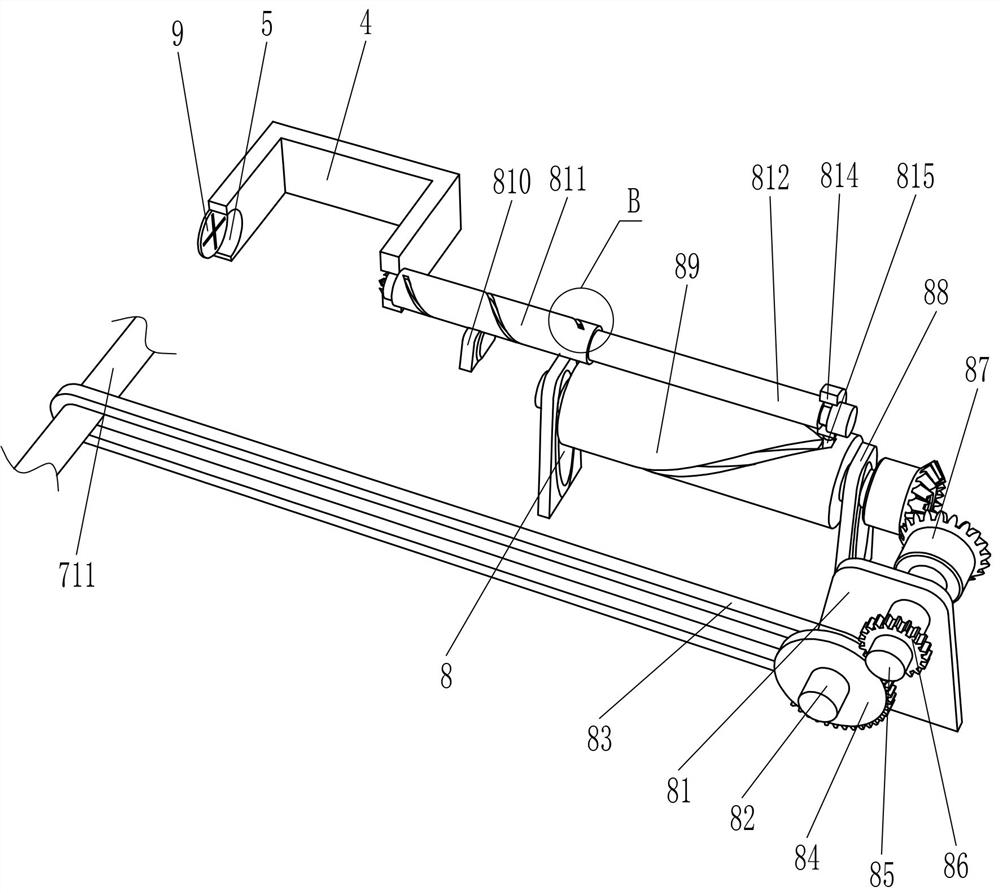
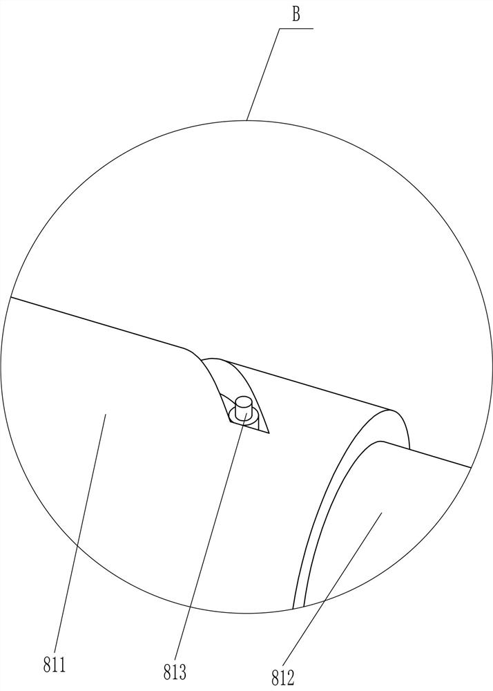
[0029] On the basis of Example 1, such as figure 1 , figure 2 , Figure 4 and Figure 6 Shown, also comprise rolling bag mechanism 8, rolling bag mechanism 8 comprises secondary transmission shaft 82, secondary belt 83, half gear 84, rotating shaft 85, cylindrical gear 86, bevel gear 87, support block 88, spiral groove post 89, Fixed block 810, spiral groove tube 811, rolling bag rod 812, runner rod 813, rotating ring 814 and latch 815, base 1 top left rear part is fixedly connected with supporting plate 81, supporting plate 81 bottom right rotating type is provided with Auxiliary transmission shaft 82, between the main transmission shaft 711 rear part and the auxiliary transmission shaft 82 middle part, a secondary belt 83 is wound around the pulley, the auxiliary transmission shaft 82 rear part is circumferentially fixed with a half gear 84, and the upper part of the support plate 81 is rotatably provided with Rotating shaft 85, the circumferential fixed sleeve of rotati...

Embodiment 3

[0032] On the basis of embodiment 1 and embodiment 2, such as figure 1 As shown, a dust-proof rubber plate 9 is also included, and the dust-proof rubber plate 9 is fixedly connected in the bag-taking hole 5, and the dust-proof rubber plate 9 cooperates with the bag roll bar 812.

[0033] Also includes a sliding material rack 10, the sliding material rack 10 is fixedly connected between the left side of the top of the base 1 and the inner and outer left sides of the discharging frame 4.

[0034] When the broken bag plate 72 moved outwards to break the cement bag, because of the effect of the dust-proof rubber plate 9, the dust of the cement was not easy to float out from the bag-taking hole 5. In this way, the dust of cement can be prevented from floating out from the bag-taking hole 5 and affecting the surrounding environment.

[0035] When the cement needs to be broken, the cement is placed on the slide frame 10, and the cement can slide into the discharge frame 4 through th...


PUM


Abstract

The invention relates to bag breaking equipment, in particular to rapid cement bag breaking equipment for a construction site. The technical problem aims to design the rapid cement bag breaking equipment for the construction site, which can replace people to break bags of cement, is convenient to operate and high in working efficiency, does not easily raise dust during bag breaking and does not influence the surrounding environment. The rapid cement bag breaking equipment for the construction site comprises a base and a guide plate, and three supporting strips are installed on one side of thebase; and the guide plate is fixedly connected among the three supporting strips far away from the base. According to the rapid cement bag breaking equipment, a bag breaking mechanism is started to begin to operate, the bag breaking mechanism operates to break bags of cement, in the bag breaking process, the cement falls into a collecting container through a discharging hopper, the bag breaking mechanism is closed to stop operating, then the broken cement bags are taken out through bag taking holes with hands, and therefore the cement bag breaking equipment can rapidly break the bags of the cement and is convenient to use and high in working efficiency.

Description

technical field [0001] The invention relates to a bag breaking device, in particular to a quick bag breaking device for cement at a construction site. Background technique [0002] Cement: powdery hydraulic inorganic gelling material. After adding water and stirring, it becomes a slurry, which can be hardened in air or in water, and can firmly bind sand, stone and other materials together. In the early years the mixture of lime and volcanic ash is very similar to lime pozzolanic cement, use it to glue concrete which made of crushed stone. After hardening, the cement not only has high strength, but also can resist the erosion of fresh water or salt water. For a long time, as an important cementing material, it is widely used in civil engineering, water conservancy, national defense and other projects. When needing to use cement, all will carry out broken bag to cement. [0003] At present, most of the cement bags are broken manually. First, the cement is pulled to the use ...

Claims


Application Information

Patent Timeline
Patent Type & Authority Applications(China)
IPC IPC(8): B65B69/00
CPCB65B69/0008
Inventor 不公告发明人
Owner 山东未来城建筑工程有限公司
Why Eureka
Try Eureka