A positioning device and working method for installing a steel bar meter in an existing pile foundation borehole

A technology of positioning device and rebar gauge, which is applied in the direction of measuring device, mechanical measuring device, infrastructure engineering, etc., can solve the problems of wasting construction time, rebar gauge falling into borehole, consumption, etc., and achieve the effect of convenient coordination

Active Publication Date: 2022-03-04
SHANDONG AGRICULTURAL UNIVERSITY
View PDF0 Cites 0 Cited by
  • Summary
  • Abstract
  • Description
  • Claims
  • Application Information

AI Technical Summary

Problems solved by technology

[0004] The inventors found that most of the current pile foundations are equipped with reinforcement gauges, and when the reinforcement timing is lowered in the existing pile foundation, it is impossible to determine whether the reinforcement gauge is in the center of the drilling hole, and the reinforcement timing is mostly manually dragged, which may occur due to improper operation. Cause steel bar meter to fall into the drill hole and other problems, consume too much labor and waste construction time, increase the cost

Method used


Image

  • A positioning device and working method for installing a steel bar meter in an existing pile foundation borehole
  • A positioning device and working method for installing a steel bar meter in an existing pile foundation borehole

Examples


Embodiment 1

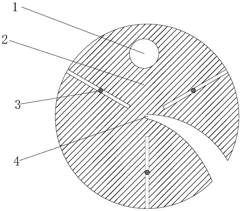
[0034] In a typical implementation of the present disclosure, such as Figure 1-Figure 2 As shown, a positioning device for installing a steel bar gauge in an existing pile foundation borehole is proposed.

[0035] It mainly includes the disc 2 and the positioning block 3 matching the disc. The disc is provided with a plurality of chutes for cooperating with the positioning block. The chute is distributed along the radial direction of the disc. The positioning block slides with the chute, and the positioning block is adjusted. The distance from the center of the disc, the positioning block presses against the inner wall of the drill hole, and the positioning block moves to push the disc to move to achieve the purpose of adjusting the position of the disc;

[0036] The chute is at least three, and the chute is distributed in different positions of the disc, and the chute corresponds to the positioning block one by one. In this embodiment, three chute are taken as an example, as...

Embodiment 2

[0057] In another typical embodiment of the present disclosure, a working method of a positioning device for installing a steel bar meter in an existing pile foundation borehole as in Embodiment 1 is given.

[0058] Include the following steps:

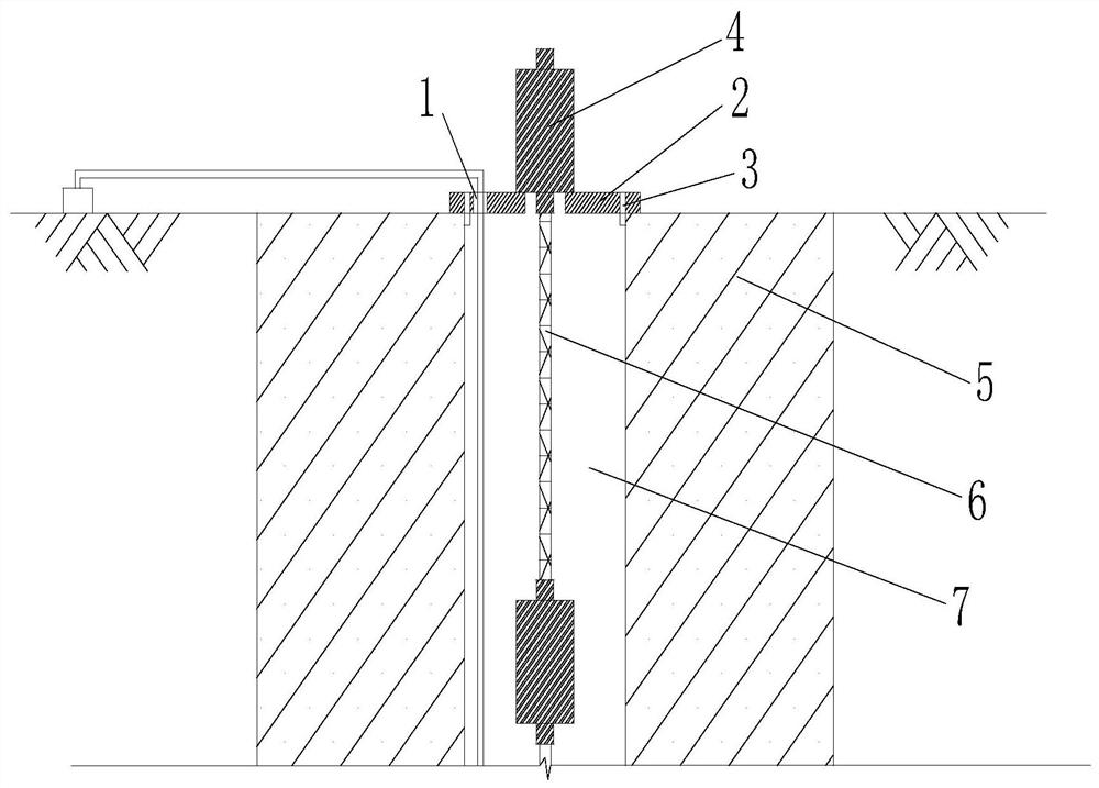
[0059] After the steel bar meter and the steel bar are connected through thread fit, they go down to the borehole of the existing pile foundation;

[0060] Arrange the disk, move the disk along the installation groove until the steel bar meter is stuck at the end of the installation groove, and the steel bar meter and the disk are distributed coaxially;

[0061] Support the disc at the opening of the drilled hole, adjust the position of the positioning block, and push the disc to change its relative position with the drilled hole until the reinforcement meter, steel bar and drilled hole are coaxially distributed.

[0062] The borehole 7 is in the center of the existing pile foundation 5, the diameter of the borehole 7 can be adjusted...


PUM


Abstract

The disclosure provides a positioning device and a working method for installing a steel bar meter in a borehole of an existing pile foundation, and relates to the field of pile foundation monitoring, including a disk, at least three chutes arranged radially along the disk, and a matching chute And the positioning block that slides along it. There is an installation groove that runs through the disc in the axial direction between two adjacent chute. The installation groove extends from the outer circumference of the disc to the center of the disc. The width of the installation groove along the centripetal direction Gradually decrease; through the disc and the positioning block to form a centering structure, cooperate with the installation groove arranged on the disc, the positioning block pushes the disc and the steel bar meter for centering arrangement, and the steel bar meter maintains the matching state with the steel bar to realize the alignment with the disc For installation, use the disc to support the steel bar meter to achieve the effect of accurate centering and installation of the steel bar meter.

Description

technical field [0001] The disclosure relates to the field of pile foundation monitoring, in particular to a positioning device and a working method for installing a steel bar meter in an existing pile foundation borehole. Background technique [0002] The statements in this section merely provide background information related to the present disclosure and may not necessarily constitute prior art. [0003] The steel bar meter is often used to be buried in hydraulic structures or other concrete structures for a long time, to measure the steel bar stress inside the structure, and to simultaneously measure the temperature of the buried point. In the pile foundation static load test, by drilling holes in the existing pile foundation and lowering the steel bar gauge in the hole, the stress data of the steel bars at different steel bar meter positions can be obtained in the static load test. [0004] The inventors found that most of the current pile foundations are equipped with...

Claims


Application Information

Patent Timeline
Patent Type & Authority Patents(China)
IPC IPC(8): G01B5/00E02D33/00
CPCE02D33/00
Inventor 程广坦丁何杰刘传孝郑帅高强张健唐亮郭常乐邱斌李传贵张阔
Owner SHANDONG AGRICULTURAL UNIVERSITY
Why Eureka
Try Eureka