Air conditioner, control method, computer equipment and readable storage medium

A control method and air conditioner technology, which are applied to mechanical equipment, control input involving air characteristics, space heating and ventilation control input, etc., and can solve problems such as energy waste, inaccurate data judgment, and human discomfort.

Inactive Publication Date: 2020-12-18
GREE ELECTRIC APPLIANCES INC
View PDF10 Cites 11 Cited by
  • Summary
  • Abstract
  • Description
  • Claims
  • Application Information

AI Technical Summary

Problems solved by technology

[0002] At present, the upper and lower air outlet cabinets disclosed in patent documents such as patents 201620942888.5 and 201610053265.7 can solve the problem of "hot head and cold feet" during heating and "cold wind blowing people" during cooling to a certain extent. However, the lower damper switch control is single, Unable to intelligently control according to the current indoor environment changes
Because the lower air outlet is close to the ground, the heat is easy to spread after the hot air blows out from the lower air outlet, resulting in a large difference in temperature between the upper and lower air outlets at a distance from the air conditioner, causing discomfort
[0003] Through the above analysis, the existing problems and defects of the prior art are as follows: (1) The control of the lower damper switch of the upper and lower air outlet cabinets in the prior art is single, and the data judgment is inaccurate. If it is not closed, it will bring a strong sense of blowing, which will cause discomfort to the human body
It also wastes energy
[0004] (2) In the existing te

Method used


Image

  • Air conditioner, control method, computer equipment and readable storage medium
  • Air conditioner, control method, computer equipment and readable storage medium
  • Air conditioner, control method, computer equipment and readable storage medium

Examples


Embodiment Construction

[0067] In order to make the object, technical solution and advantages of the present invention more clear, the present invention will be further described in detail below in conjunction with the examples. It should be understood that the specific embodiments described here are only used to explain the present invention, not to limit the present invention.

[0068] Aiming at the problems existing in the prior art, the present invention provides an air conditioner, a control method, computer equipment and a readable storage medium. The present invention will be described in detail below in conjunction with the accompanying drawings.

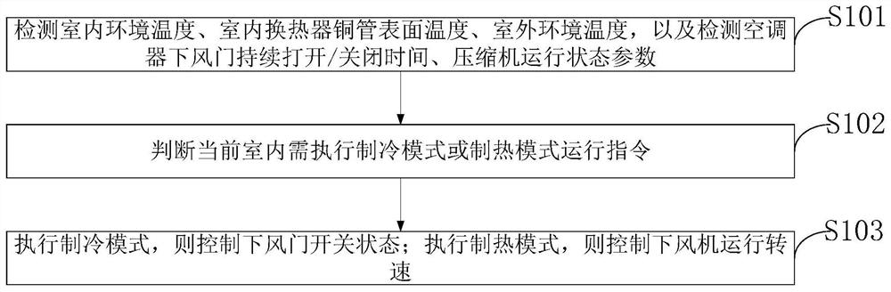
[0069] As shown in the figure, the air conditioner control method provided by the embodiment of the present invention includes:

[0070] S101 , detecting the indoor ambient temperature, the surface temperature of the copper pipe of the indoor heat exchanger, and the outdoor ambient temperature, and detecting the continuous opening / closing time of t...


PUM


Abstract

The invention belongs to the technical field of air conditioner control, and discloses an air conditioner, a control method, computer equipment and a readable storage medium. The control method comprises the following steps of detecting the indoor environment temperature, the surface temperature of a copper pipe of an indoor heat exchanger and the outdoor environment temperature, and detecting thecontinuous opening/closing time of a lower air door of the air conditioner and the running state parameters of a compressor; judging that a refrigerating mode or heating mode operation instruction needs to be executed indoors currently, executing a refrigerating mode, and controlling the opening and closing states of the lower air door; and executing a heating mode, and controlling the running rotating speed of the lower fan. In the refrigeration mode, discomfort caused by air blowing feeling can be reduced on the basis that indoor temperature drop is met, in the heating mode, indoor thermalcomfort can be improved, and the purpose of saving energy is achieved. In the refrigeration mode, the discomfort brought to a user by the air blowing feeling is greatly reduced. In the heating mode, the temperature difference between the head and the feet is reduced by 0.97-1.71 DEG C at the position 2 m away from the air conditioner, and the heating comfort is greatly improved.

Description

technical field [0001] The invention belongs to the technical field of air conditioning control, and in particular relates to an air conditioner, a control method, computer equipment and a readable storage medium. Background technique [0002] At present, the upper and lower air outlet cabinets disclosed in patent documents such as patents 201620942888.5 and 201610053265.7 can solve the problem of "hot head and cold feet" during heating and "cold wind blowing people" during cooling to a certain extent. However, the lower damper switch control is single, It cannot be intelligently controlled according to changes in the current indoor environment. Because the lower air outlet is close to the ground, the heat is easy to spread after the hot air blows out from the lower air outlet, resulting in a large difference in temperature between the upper and lower air outlets at a distance from the air conditioner, causing discomfort. [0003] Through the above analysis, the existing ...

Claims


Application Information

Patent Timeline
IPC IPC(8): F24F11/74F24F11/77F24F11/64F24F110/10F24F110/12F24F140/40
CPCF24F11/64F24F11/74F24F11/77F24F2110/10F24F2110/12F24F2140/40Y02B30/70
Inventor 梁玉林邹云辉刘雷明陈锐东
Owner GREE ELECTRIC APPLIANCES INC
Why Eureka
Try Eureka