Driving wheel rotating speed control method and system

A speed control and drive wheel technology, applied in the direction of control drive, control devices, electric vehicles, etc., can solve the problems of differential damage, ablation, and unresolved problems, so as to avoid damage and ablation and improve maneuverability Effect

Active Publication Date: 2020-12-22
GREAT WALL MOTOR CO LTD
View PDF6 Cites 4 Cited by
  • Summary
  • Abstract
  • Description
  • Claims
  • Application Information

AI Technical Summary

Problems solved by technology

At this time, if the driver's torque request is large, the speed difference between the two driving wheels will easily exceed the maximum speed difference between the two driving wheels that the differential can withstand, which will eventually cause damage and ablation of the differential
[0003] The inventor of the present application found in the process of realizing the present invention that there is no solution to the above-mentioned problems in the prior art

Method used


Image

  • Driving wheel rotating speed control method and system
  • Driving wheel rotating speed control method and system
  • Driving wheel rotating speed control method and system

Examples


Embodiment 1

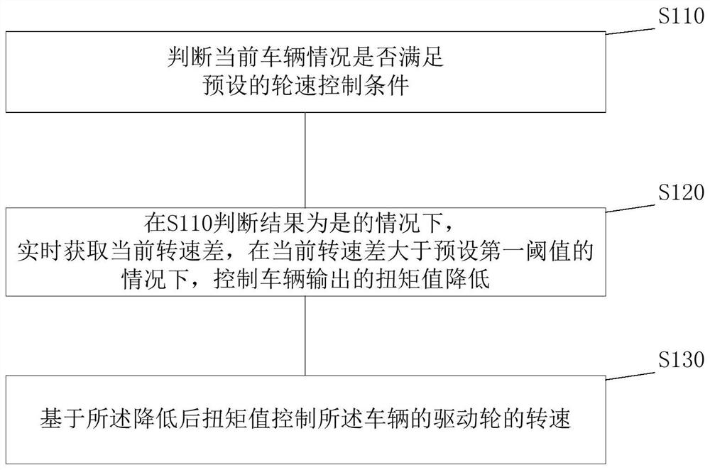
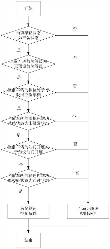
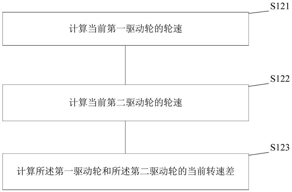
[0036] Figure 1a It is a flow chart of the method for controlling the speed of the driving wheel in Embodiment 1, which mainly describes how to control the speed of the driving wheel to avoid damage to the differential caused by continuous increase of the speed of the driving wheel in the case of unilateral slippage. Figure 1b It is the judging method of the wheel speed control condition in the first embodiment. Figure 1c It is the calculation method of the rotational speed difference of the two driving wheels in the first embodiment.

[0037] Such as Figure 1a As shown, the present invention also provides a driving wheel speed control method, and the driving wheel speed control method may include:

[0038] S110, judging whether the current vehicle condition satisfies a preset wheel speed control condition.

[0039] Wherein, the preset wheel speed control conditions can be adjusted according to actual conditions, and the corresponding current vehicle conditions will also ...

Embodiment 2

[0059] figure 2 It is the flowchart of the second embodiment, wherein the second embodiment is a further improvement made on the basis of the first embodiment. Specifically, a further improvement is made on "controlling the reduction of the torque value output by the vehicle" in the first embodiment. The improved solution mainly involves two steps, which are specifically described as follows. image 3 It is the specific flow chart of "calculating the target torque value". Figure 4 It is a specific flowchart of "controlling the torque value output by the vehicle to decrease to the target torque value".

[0060] S210, calculating a target torque value.

[0061] Wherein, the manner of calculating the target torque value may include the following S211-S213. S211-S213 will be used for specific description below.

[0062] S211, according to the preset first compensation ratio table recording the correspondence between the rotation speed difference and the first torque coeffic...

Embodiment 3

[0084] Embodiment 3 is a further improvement made on the basis of Embodiment 2, which mainly includes when the current speed difference is greater than the preset first threshold (marking that the vehicle is in or tends to one-sided slipping state) , to control the situation after the torque value output by the vehicle is reduced. Embodiment 3 mainly includes two possible situations, as described below. in, Figure 5 It is a specific flow chart for further improvement of the case 1 of the third embodiment "controlling the output torque value of the vehicle to change to the required torque value of the vehicle";

[0085] Case 1: When the current rotational speed difference is less than a preset second threshold (marking that the vehicle is not in or tends to one-side slipping state), control the output torque value of the vehicle to change to the required torque value of the vehicle.

[0086] Wherein, in the first case, the current rotational speed difference is collected in ...


PUM


Abstract

The invention relates to the technical field of vehicle control, and provides a driving wheel rotating speed control method and system. The method comprises the steps that: whether a current vehicle condition meets a preset wheel speed control condition or not is judged, and if the current vehicle condition meets the preset wheel speed control condition, the following step is executed: a current rotating speed difference of two driving wheels connected to the same differential mechanism of a vehicle is obtained in real time, and under the condition that the current rotating speed difference islarger than a preset first threshold value, a torque value output by the vehicle is controlled to be reduced; and the driving wheel rotating speed of the vehicle is controlled based on the reduced torque value. According to the driving wheel rotating speed control method and system, damage and ablation of the differential mechanism are prevented.

Description

technical field [0001] The invention relates to the technical field of vehicle control, in particular to a driving wheel rotational speed control method and system thereof. Background technique [0002] When the existing vehicle is running on an extreme road surface with low adhesion, when the adhesion on one side of the vehicle is too small, once the motor controller controls the driving force generated by the drive motor to be greater than the friction between the tire on one side and the ground, The unilateral tire will slip on one side. At this time, if the driver's torque request is large, the speed difference between the two driving wheels will easily exceed the maximum speed difference between the two driving wheels that the differential can bear, eventually causing damage and ablation of the differential. [0003] In the process of realizing the present invention, the inventors of the present application found that there is no solution to the above-mentioned problem...

Claims


Application Information

Patent Timeline
Patent Type & Authority Applications(China)
IPC IPC(8): B60L15/20
CPCB60L15/20B60L2240/461Y02T10/72
Inventor 王银磊邓伟峰亢通常笑陈淑江侯文涛
Owner GREAT WALL MOTOR CO LTD
Why Eureka
Try Eureka