
Folding wing unfolding rotating shaft mechanism

A wing unfolding and rotating shaft technology, which is applied to the wing rotation of drones and the aviation field, can solve the problems of slow opening response speed, etc., and achieve the effect of reliable connection, simple connection method and compact structure

Pending Publication Date: 2020-12-22
XIAN LINGKONG ELECTRONICS TECH CO LTD
View PDF0 Cites 6 Cited by
  • Summary
  • Abstract
  • Description
  • Claims
  • Application Information

AI Technical Summary

Problems solved by technology

In the existing barrel-type launch aircraft, the wing expansion mechanism is mostly driven by torsion springs, which has the problem of slow opening response speed

Method used


Image

  • Folding wing unfolding rotating shaft mechanism
  • Folding wing unfolding rotating shaft mechanism
  • Folding wing unfolding rotating shaft mechanism

Examples


Embodiment 1

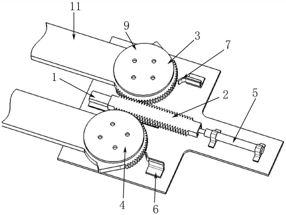
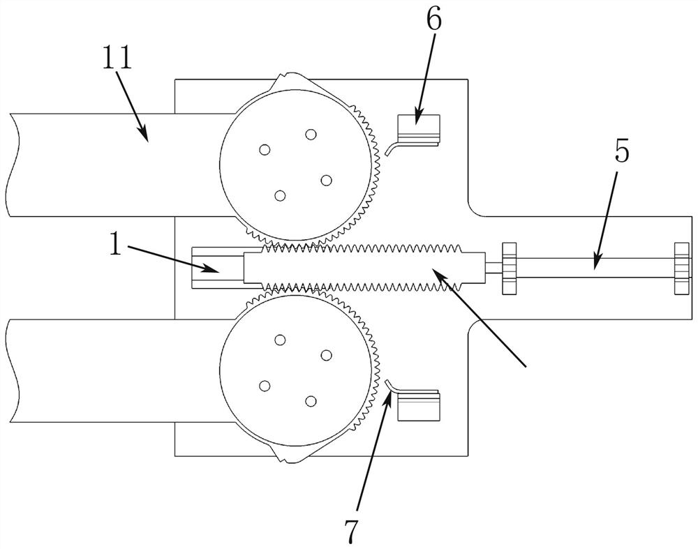
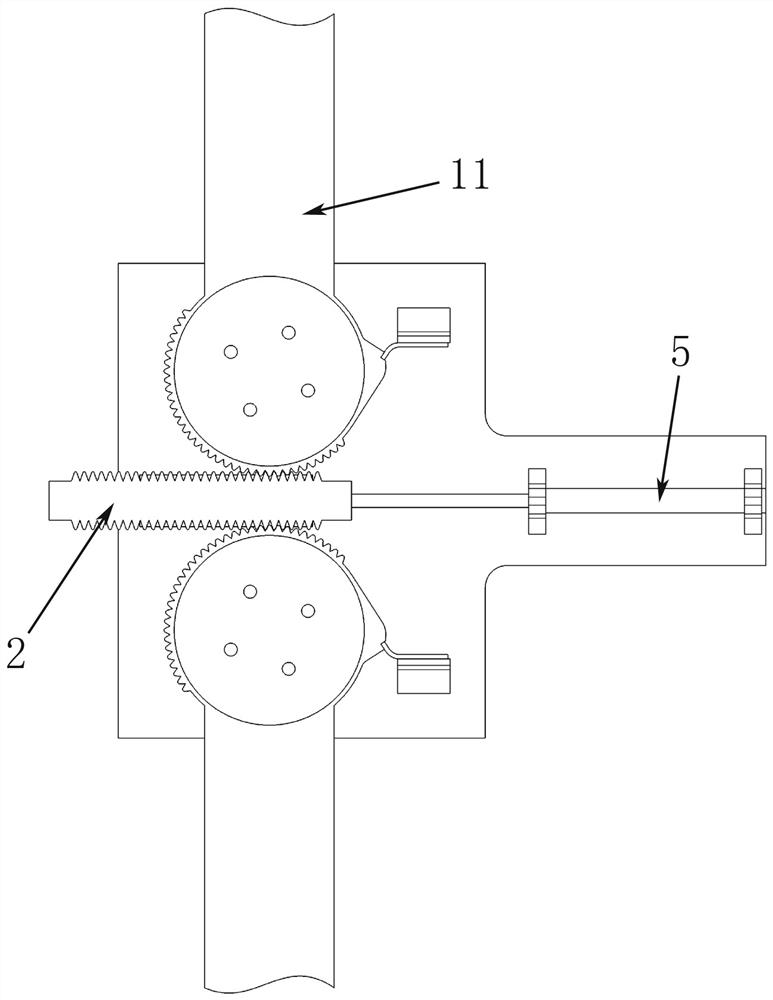
[0044] Such as figure 1 As mentioned above, the wing root 11 of the wing is an aluminum alloy machined part, and the left and right wings are respectively fixed on the connecting boss 10 of the connecting base, and fixed by the rotating shaft cover plate 9, and the rotating shaft cover plate 9 is protruded by the fixing bolt and the rotating shaft. station connection. Planar thrust needle roller bearings 8 are arranged between the lower end surface of the wing root 11 and the connecting base, and between the upper surface of the wing root 11 and the shaft cover 9 to ensure that the wing root 11 can rotate normally when the wing is subjected to lift.

[0045] In order to drive the wings to rotate and open, the first teeth are arranged on the arc length of the outer circle of the left and right wing roots 11 exceeding 1 / 4 of the circle. Between the two wing shafts, a rack 2 with teeth on both side walls of the wing root 11 is arranged, and the first tooth of the rack 2 meshes w...


PUM


Abstract

The invention belongs to the technical field of aviation, particularly relates to the technical field of unmanned aerial vehicle wing rotation, and particularly relates to a folding wing unfolding rotating shaft mechanism. The folding wing unfolding rotating shaft mechanism comprises wings and a connecting base fixed to an unmanned aerial vehicle, and two connecting bosses are fixedly arranged onthe connecting base. The two connecting bosses are rotationally connected with the wing root of one wing separately. A sliding rail is fixedly arranged in the connecting base between the connecting bosses. Driving force is provided through a gunpowder actuator cylinder, a rack is pushed to move, a first gear and a second gear are driven to rotate synchronously, and the left wing and the right wingrotate at the same time to be unfolded quickly. The left wing and the right wing adopt independent rotating shafts, and compared with a coaxial unfolding mechanism, the connecting mode is simple, andreliable wing root connection is easily ensured. Compared with multi-connecting-rod force transmission, the transmission of the folding wing unfolding rotating shaft mechanism is achieved in a gear and rack meshing mode, so that the structure is compact, and rotation is more stable.

Description

technical field [0001] The invention relates to the field of aviation technology, in particular to the field of UAV wing rotation technology, and in particular to a folding wing unfolding shaft mechanism. Background technique [0002] The barrel-type launch UAV, the wing shaft mechanism is a difficult point. It needs the shaft mechanism to be deployed quickly in a short period of time, and the left and right wings are deployed synchronously, and can withstand the load of the wing under various load conditions. It is also necessary to realize position locking under the wing unfolded state. In the existing barrel-type launching aircraft, the wing expansion mechanism is mostly driven by torsion springs, which has the problem of slow opening response speed. Contents of the invention [0003] In order to solve the above problems, the present invention provides a folding wing unfolding shaft mechanism. Compared with the existing structure, it has advantages in the connection be...

Claims


Application Information

Patent Timeline
Patent Type & Authority Applications(China)
IPC IPC(8): B64C3/56
CPCB64C3/56
Inventor 张玺雷黎明晁向飞李沙妮沈洋
Owner XIAN LINGKONG ELECTRONICS TECH CO LTD
Learn More