Oil tank heating device

A heating device and oil tank technology, applied in the field of machinery, can solve the problems of small contact area, large heat loss, energy waste, etc., and achieve the effect of not easy to block

Pending Publication Date: 2020-12-22
HUNAN NSG ELECTRICAL APPLIANCE
View PDF0 Cites 0 Cited by
  • Summary
  • Abstract
  • Description
  • Claims
  • Application Information

AI Technical Summary

Problems solved by technology

[0002] Existing oil tanks usually install heating pipes on the shell when heating the oil, but this heating method has a small contact area with the oil, so the heat conduction efficiency is not high. In addition, the heat loss is large, resulting in energy waste

Method used


Image

  • Oil tank heating device

Examples


Embodiment 1

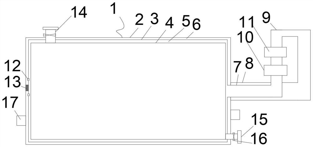
[0014] Such as figure 1 The oil tank heating device shown includes an oil tank body 1, and the oil tank body 1 includes an inner shell 2, a middle shell 3 and an outer shell 4; a heating gap 5 is formed between the inner shell 2 and the middle shell 3; the middle shell 3 and the shell layer 4 are formed with a backflow gap 6; the right end of the heating gap 5 is connected with a liquid inlet pipe 7, and the backflow gap 6 is connected with a backflow pipe 8, and the backflow pipe 8 is set outside the liquid inlet pipe 7; The flow pipe 8 communicates with the liquid inlet pipe 7 through the circulation pipe 9; the circulation pump 10 and the heater 11 are installed on the circulation pipe 9;

[0015] The left end of the middle shell 3 is fixedly connected with the shell layer 4 through the fixing block 13 . The top of the oil tank body 1 is connected with a liquid inlet pipe 14, and the bottom is connected with a liquid outlet pipe 15; both the liquid inlet pipe 14 and the li...


PUM


Abstract

The invention discloses an oil tank heating device. The oil tank heating device comprises an oil tank body, and the oil tank body comprises an inner shell, a middle layer shell and an outer shell layer. A heating gap is formed between the inner shell and the middle layer shell. A reflux gap is formed between the middle layer shell and the outer shell layer. The right end of the heating gap communicates with a liquid inlet pipe, the reflux gap communicates with a reflux pipe, and the reflux pipe is arranged outside the liquid inlet pipe in a sleeving mode. The reflux pipe communicates with theliquid inlet pipe through a circulating pipe. A circulating pump and a heater are mounted on the circulating pipe. The left end of the reflux gap and the left end of the heating gap communicate with each other through a communicating hole. According to the oil tank heating device, the reflux gap is used for preserving the heat of the heating gap, due to the fact that the temperature of the refluxgap is lower, heat loss is reduced, and heat loss is effectively reduced; and moreover, oil in the oil tank can flow through overall heating of the gap layer and ultrasonic vibration, and the heat transfer efficiency is improved.

Description

technical field [0001] The invention belongs to the field of machinery, in particular to an oil tank heating device. Background technique [0002] Existing oil tanks usually install heating pipes on the shell when heating the oil, but this heating method has a small contact area with the oil, so the heat conduction efficiency is not high. In addition, the heat loss is large, resulting in energy waste. Contents of the invention [0003] In order to solve the above problems, the present invention provides an oil tank heating device. The present invention uses the backflow gap to insulate the heating gap. Because the backflow gap temperature is lower, the heat loss is reduced, thereby effectively reducing the heat loss, and the gap layer is heated as a whole, and the oil in the oil tank is made to flow through ultrasonic vibration. Thereby increasing the heat transfer efficiency. [0004] For reaching above-mentioned technical effect, technical scheme of the present inventi...

Claims


Application Information

Patent Timeline
Patent Type & Authority Applications(China)
IPC IPC(8): B65D88/74B65D90/00F24H7/02
CPCB65D88/74B65D90/00F24H7/0233
Inventor 庞佳汤勇
Owner HUNAN NSG ELECTRICAL APPLIANCE
Why Eureka
Try Eureka