
Device for protecting strain test bridge circuit on surface of steel plate and mounting method

A technology for strain testing and installation methods, which is applied in the testing of infrastructure, construction, infrastructure engineering, etc., to achieve the effect of convenient installation and reduced interference

Pending Publication Date: 2020-12-22
CCCC FOURTH HARBOR ENG CO LTD +2
View PDF0 Cites 2 Cited by
  • Summary
  • Abstract
  • Description
  • Claims
  • Application Information

AI Technical Summary

Problems solved by technology

[0004] The purpose of the present invention is to provide a device and installation method for steel plate surface strain test bridge protection, aiming to solve the shortcomings of the existing method of installing strain test bridges on the steel plate surface

Method used


Image

  • Device for protecting strain test bridge circuit on surface of steel plate and mounting method
  • Device for protecting strain test bridge circuit on surface of steel plate and mounting method
  • Device for protecting strain test bridge circuit on surface of steel plate and mounting method

Examples


Embodiment Construction

[0043] In order to make the purpose, technical solutions and advantages of the embodiments of the present invention clearer, the technical solutions in the embodiments of the present invention will be clearly and completely described below in conjunction with the drawings in the embodiments of the present invention. Obviously, the described embodiments It is a part of embodiments of the present invention, but not all embodiments. The components of the embodiments of the invention generally described and illustrated in the figures herein may be arranged and designed in a variety of different configurations.

[0044] Accordingly, the following detailed description of the embodiments of the invention provided in the accompanying drawings is not intended to limit the scope of the claimed invention, but merely represents selected embodiments of the invention. Based on the embodiments of the present invention, all other embodiments obtained by persons of ordinary skill in the art wi...


PUM


Abstract

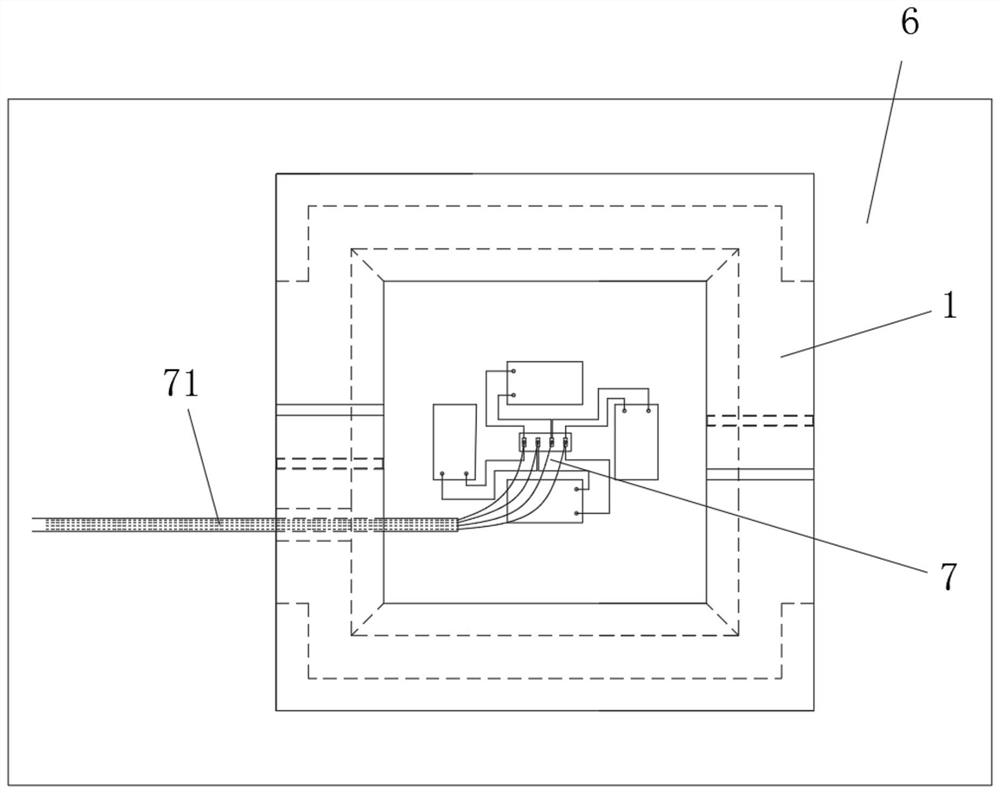
The invention provides a device for protecting a strain test bridge circuit on the surface of a steel plate and a mounting method. The device comprises two half frames, one end of each half frame is provided with a protrusion, the other end of each half frame is provided with a groove, and the protrusion of any half frame is connected with the groove of the other half frame in an inserted mode, sothat the two half frames are connected into a frame assembly; the frame assembly is used for being mounted on the surface of the to-be-tested steel plate, after the frame assembly is mounted on the surface of the to-be-tested steel plate, a mounting space used for mounting the strain test bridge circuit is defined by the two half frames on the surface of the to-be-tested steel plate, and the mounting space is filled with a first sealing layer and a second sealing layer wrapping the outer side of the first sealing layer; and one of the two half frames is provided with a first wire groove whichmakes the mounting space communicate with the outside, and the first wire groove is filled with the second sealing layer. The defect of an existing mounting mode of the strain test bridge circuit onthe surface of the steel plate is overcome.

Description

technical field [0001] The invention belongs to the technical field of pile foundation engineering testing, in particular to a device and installation method for steel plate surface strain testing bridge road protection. Background technique [0002] Steel pipe piles and steel sheet piles are commonly used pile foundation forms in engineering, which are generally driven into the soil layer by impact, vibration or static pressure. Mastering the development law of soil resistance around piles under the action of pile driving dynamic load or superstructure load is the key to analyze pile bearing capacity, carry out pile foundation design and calculation, and predict the feasibility of pile sinking. The law of soil resistance is very complicated. In actual engineering, strain sensors are installed at multiple points along the pile body to obtain the strain distribution data of the pile body under load conditions, so as to indirectly calculate the soil resistance of the pile sect...

Claims


Application Information

Patent Timeline
Patent Type & Authority Applications(China)
IPC IPC(8): E02D33/00
CPCE02D33/00
Inventor 吕述晖桑登峰吴佳琪
Owner CCCC FOURTH HARBOR ENG CO LTD
Learn More