Guide claw release mechanism internally provided with transmission shaft

A release mechanism and transmission shaft technology, applied in wellbore/well parts, earthwork drilling and production, etc., can solve the problems that the transmission shaft cannot be arranged in the center, takes up a lot of space for the instrument, and has a large volume, so as to achieve quick start, high acceptance, and Ease of use

Pending Publication Date: 2020-12-22
贵州航天凯山石油仪器有限公司
View PDF0 Cites 0 Cited by
  • Summary
  • Abstract
  • Description
  • Claims
  • Application Information

AI Technical Summary

Problems solved by technology

[0004] The object of the present invention is to provide a guide claw release mechanism with a transmission shaft inside to solve the problems of the existing guide claw release mechanism, which are large in size, occupy a lot of equipment space, and the drive shaft cannot be arranged in the center, so as to overcome the problems existing in the prior art. lack of

Method used


Image

  • Guide claw release mechanism internally provided with transmission shaft
  • Guide claw release mechanism internally provided with transmission shaft
  • Guide claw release mechanism internally provided with transmission shaft

Examples


Embodiment Construction

[0020] The present invention will be further described in detail below in conjunction with the accompanying drawings and embodiments.

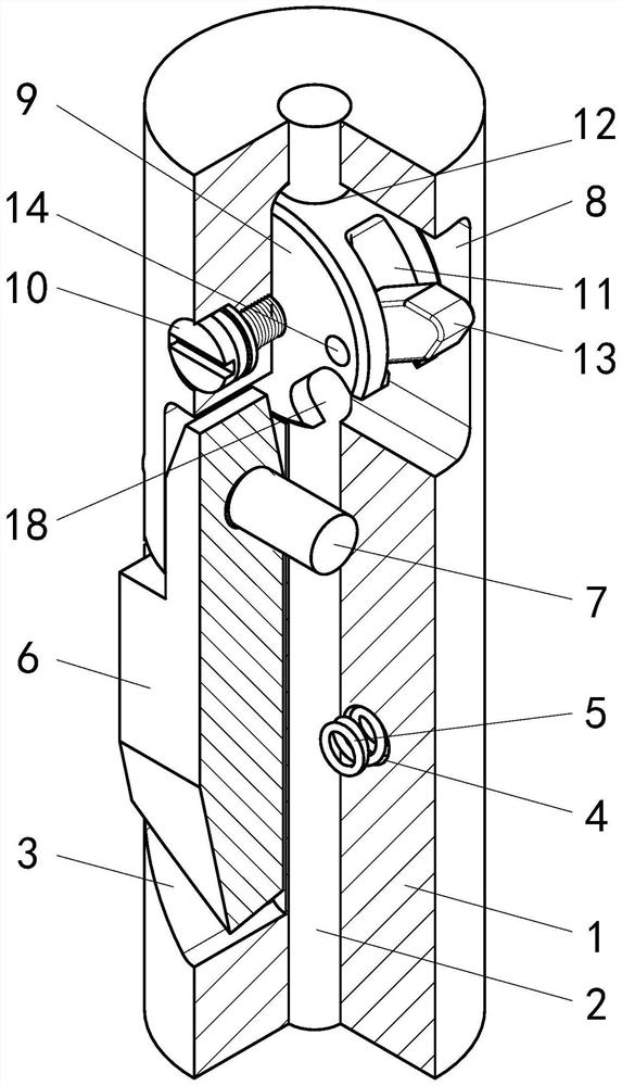
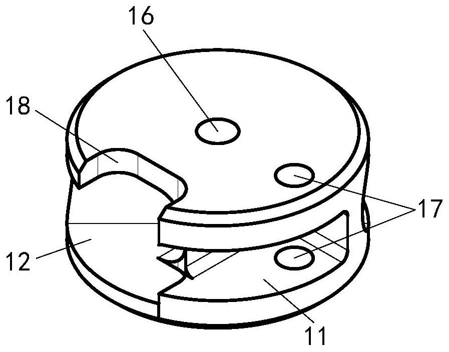
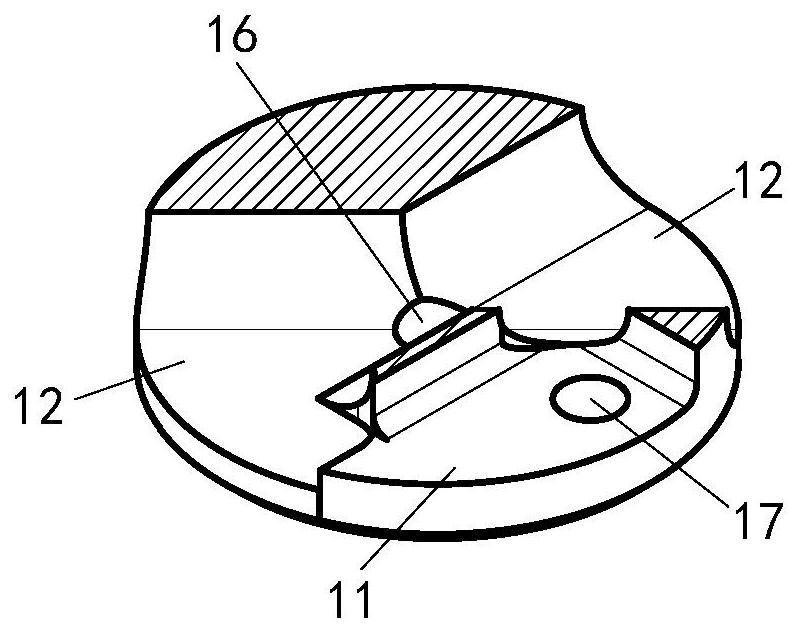
[0021] A kind of guiding pawl release mechanism that is provided with transmission shaft inside the present invention, as Figure 1 to Figure 7 As shown, it includes a cylindrical base 1; the central hole 23 of the cylindrical base 1 is provided with a transmission shaft 2, and the base 1 on one side of the transmission shaft 2 is provided with a guide claw groove 3, and the bottom of the guide claw groove 3 is provided with a spring hole 4. The spring hole 4 is provided with a spring 5; the guide claw groove 3 is provided with a guide claw 6; the guide claw 6 is hinged with the cylindrical base 1 through the guide claw pin 7; The cam groove 8 is provided with a cam 9; the cam 9 is connected to the cylindrical base 1 by a fixed angle through a pair of cam screws 10; the cam 9 is provided with a collision switch groove 11 and a transmission sha...


PUM


Abstract

The invention discloses a guide claw release mechanism internally provided with a transmission shaft. The guide claw release mechanism comprises a cylindrical base (1). A transmission shaft (2) is arranged in a central hole of the cylindrical base, a guide claw groove (3) is formed in the position, on one side of the transmission shaft, of the cylindrical base, and a guide claw (6) is arranged inthe guide claw groove; a cam groove (8) is formed in the position, above the guide claw, of the cylindrical base, and a cam (9) is arranged in the cam groove; a collision switch groove (11) and a transmission shaft groove (12) are formed in the cam, and a collision switch (13) is arranged in the collision switch groove; the collision switch is hinged with the cam through a collision switch pin, and a torsional spring (15) is arranged between the collision switch and the collision switch groove; and the transmission shaft penetrates through the transmission shaft groove. The guide claw releasemechanism is suitable for power transmission at the center position of the guide claw release mechanism, and can also be used for other similar structures needing to use the center position, such as pressure transmission at the center position and avoidance of certain parts at the center position.

Description

technical field [0001] The invention relates to a guide claw release mechanism provided with a drive shaft inside, and belongs to the technical field of downhole instrument structures. Background technique [0002] In oilfield water well testing work, many instruments need to eccentrically dock the eccentric arm of the instrument with the eccentric hole on the downhole tool, and the guide claw is the key mechanism to realize the guiding and docking of the instrument and the downhole tool. The basic principle and general structure of how the guide claw and the shoulder of the downhole tool realize rotary steering is a technology commonly used in oilfields. However, limited by various factors such as the outer diameter of the instrument and function settings, the existing guide claw release structure has the following disadvantages: [0003] The existing guide claw release mechanism is bulky and takes up a lot of space in the instrument; the remaining space of the instrument ...

Claims


Application Information

Patent Timeline
IPC IPC(8): E21B23/00
CPCE21B23/00
Inventor 王守舵冯贵洪胡腾孙冬青
Owner 贵州航天凯山石油仪器有限公司
Why Eureka
Try Eureka