

Pressure test tool for floating head heat exchanger
A heat exchanger and pressure test technology, which is applied in the testing of machines/structural components, instruments, measuring devices, etc., can solve the problems such as the difficulty in manufacturing the pressure test of the tube head of the floating head heat exchanger, and achieve safe and reliable performance and pre-tightening Good effect and easy installation
Pending Publication Date: 2020-12-22
大连派思燃气设备有限公司
View PDF0 Cites 0 Cited by
- Summary
- Abstract
- Description
- Claims
- Application Information
AI Technical Summary
Problems solved by technology
However, the pressure test of the tube head of the floating head heat exchanger is a difficult point in manufacturing
Method used
View moreImage
Smart ImageViewing Examples

Examples
Embodiment Construction
[0010] Embodiment is illustrated below in conjunction with accompanying drawing:
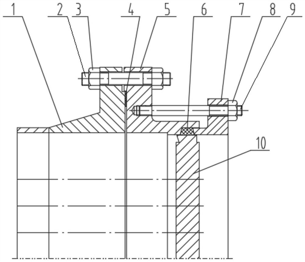
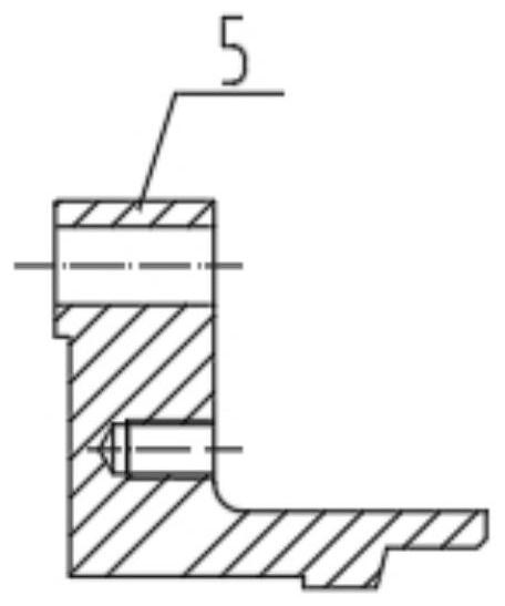
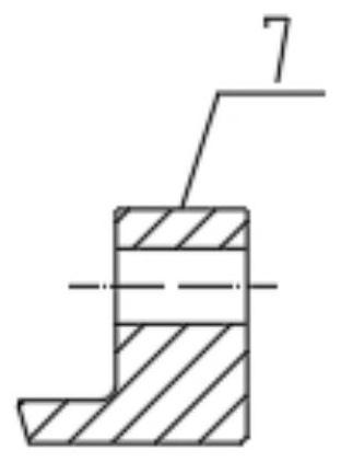
[0011] A pressure test tooling for a floating head heat exchanger, comprising: equipment flange 1, equipment stud 2, equipment nut 3, gasket 4, tooling flange 5, packing 6, gland 7, pressure test nut 8, pressure test Use bolts 9 and floating tube sheets 10; connect equipment flange 1 and tooling flange 5 through equipment studs 2 and equipment nuts 3, and connect tooling flange 5 and gland 7 through pressure test bolts 9 and pressure test nuts 8 , the equipment flange 1 and the tooling flange 5 are sealed by the gasket 4, and the floating tube sheet 10 is sealed with the tooling flange 5 and the gland 7 by the packing 6.
Login to View More PUM
 Abstract
The invention provides a pressure test tool for a floating head heat exchanger. The pressure test tool comprises an equipment flange, an equipment stud, an equipment nut, a gasket, a tool flange, a filler, a gland, a pressure test nut, a pressure test bolt and a floating tube plate, wherein the equipment flange and the tool flange are connected through the equipment stud and the equipment nut; thetool flange and the gland are connected through the pressure test bolt and the pressure test nut; the equipment flange and the tool flange are sealed through the gasket; and the floating tube plate,the tool flange and the gland are sealed through the filler. The pressure test tool has the advantages of being convenient to install, good in pre-tightening effect, safe and reliable in performance and capable of being repeatedly used.
Description
technical field [0001] The invention relates to a pressure test tool for a floating head heat exchanger used in the petrochemical industry. Background technique [0002] With the development of the chemical industry, more and more heat exchangers are used in the petrochemical industry, among which floating head heat exchangers are used more and more. This kind of heat exchanger is easy to clean and maintain, and can deal with uncleanness and easy scaling medium, and can withstand high temperature and high pressure. But the pressure test of the tube head of the floating head heat exchanger is a difficult point in the manufacture. Contents of the invention [0003] In order to overcome the disadvantages of the prior art, the invention provides a pressure test tool for a floating head heat exchanger. [0004] The technical solution of the present invention is: a pressure test tooling for a floating head heat exchanger, which is characterized in that it includes: equipment f...
Claims
Login to View More Application Information
Patent Timeline
 Patent Type & AuthorityApplications(China)
IPC IPC(8): G01M13/00G01N3/08G01N3/02
CPCG01M13/00G01N3/08G01N3/02
Inventor李继峰张玉龙张保健张雪王石贺春任春嫒
Owner大连派思燃气设备有限公司