Check patentability & draft patents in minutes with Patsnap Eureka AI!

Laminated battery

A laminated, battery technology, used in secondary batteries, secondary battery manufacturing, battery pack components, etc., can solve the problem of damage to the insulating coating layer, pinholes in the insulating coating layer, electrode plates and external packaging. Short circuit and other problems, to achieve the effect of improving reliability, suppressing capacity reduction, and preventing short circuit

Pending Publication Date: 2020-12-22
SEKISUI CHEM CO LTD
View PDF2 Cites 0 Cited by
  • Summary
  • Abstract
  • Description
  • Claims
  • Application Information

AI Technical Summary

Problems solved by technology

[0008] However, defects such as pinholes sometimes occur on the insulating coating layer
For example, the insulating coating layer may be partially damaged due to contact with the edge of the electrode plate
Also, in the event of a defect in the insulating coating layer, a short circuit occurs between the electrode plate and the outer package, so that the laminated battery cannot perform a predetermined function.

Method used


Image

  • Laminated battery
  • Laminated battery
  • Laminated battery

Examples


no. 1 Embodiment approach

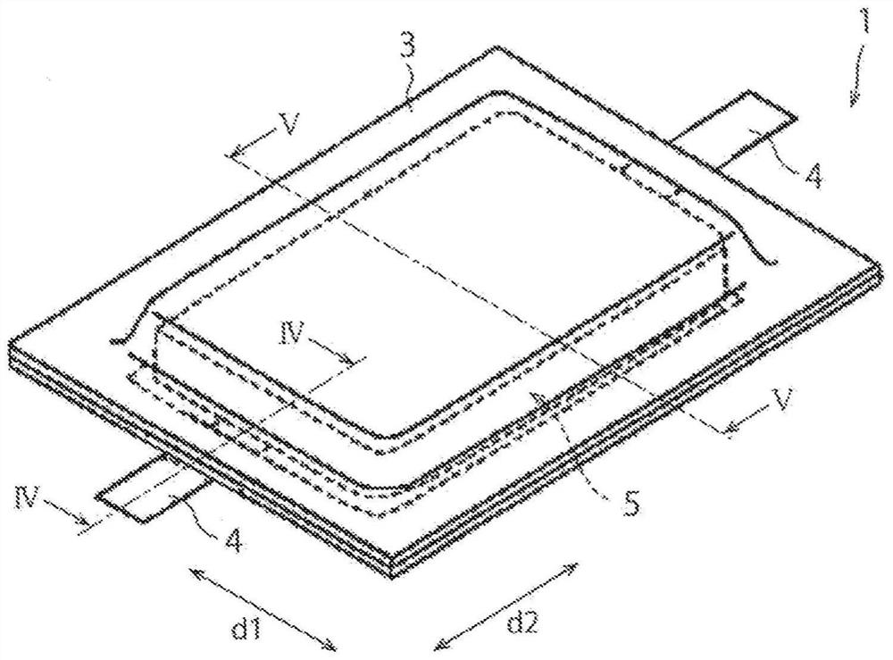
[0096] Figure 1 to Figure 8 It is a figure for demonstrating the 1st Embodiment of the laminated electrode based on 1st invention. figure 1 is a perspective view showing a specific example of a laminated battery. Such as figure 1 As shown, the laminated battery 1 has: an outer packaging body 3, a membrane electrode assembly 5 accommodated in the outer packaging body 3, and a wire connected to the membrane electrode assembly 5 and protruding from the inside of the outer packaging body 3 to the outside. slice 4. Such as figure 2 As shown, the membrane electrode assembly 5 has first electrode sheets 10 and second electrode sheets 20 alternately stacked. figure 1 In the example shown, the laminated battery 1 has an overall flat shape extending along a first direction d1 as a width direction and a second direction d2 as a length direction.

[0097] Hereinafter, description will be made by taking the stacked battery 1 as an example to constitute a lithium ion secondary batter...

no. 2 Embodiment approach

[0163] Figure 9 to Figure 16 It is a figure for demonstrating the 2nd Embodiment of the laminated electrode based on 2nd invention.

[0164] In the second embodiment described below, the laminated battery 101 has an outer package 140 , a membrane electrode assembly 105 accommodated in the outer package 140 , and a The lug 103 protruding outward. Among them, the membrane electrode assembly 105 has first electrode plates 110 and second electrode plates 120 stacked alternately, and an insulator 130 located between the first electrode plates 110 and the second electrode plates 120 . In such a laminated battery 101, in the manufacture of the plurality of electrode plates 110, 120 constituting the membrane-electrode assembly 105, the electrode plates 110 may be damaged due to the decrease in positioning accuracy and the positional displacement of the electrode plates 110, 120 during use. , 120 and the external packaging body 140 are short-circuited. The laminated battery 101 in ...


PUM

PropertyMeasurementUnit
Thicknessaaaaaaaaaa
Thicknessaaaaaaaaaa

Abstract

This laminated battery 1 is provided with: a plurality of electrode plates 10, 20 laminated in a lamination direction dL; and an insulation sheet 30. The insulation sheet 30 is alternately folded in awidthwise direction d1 that is not parallel to the lamination direction dL, and is disposed between two electrode plates 10, 20 that are adjacent to each other in the lamination direction dL. Gaps 40are provided between folded parts 33, 34 of the insulation sheet 30, and ends 10a, 20b of the electrode plates 10, 20 which face the corresponding folded parts in the widthwise direction d1. The length between the folded parts 33, 34 along the widthwise direction d1 and the ends 10a, 20b of the electrode plates 10, 20 which face the corresponding folded parts 33, 34 is at least five times the thickness of the corresponding electrode plates 10, 20.

Description

technical field [0001] The present invention relates to laminated batteries. Background technique [0002] As described in JP2014-165055A and JP2013-182715A, laminated batteries in which positive plates and negative plates are alternately stacked are widely used. An example of a stacked battery is a lithium ion secondary battery. Lithium-ion secondary batteries, compared with other types of laminated batteries, have a large capacity as one of their characteristics. Lithium-ion secondary batteries having such characteristics are currently expected to be further spread in various applications such as vehicle-mounted applications and stationary residential applications. [0003] In a laminated battery, for example, ions are charged and discharged by moving between positive and negative plates through an electrolyte solution. For example, in the case of a lithium ion secondary battery, lithium ions in the electrolytic solution move from the positive electrode to the negative ...

Claims


Application Information

Patent Timeline
IPC IPC(8): H01M10/04H01M2/16H01M2/18H01M10/0583H01M10/0585H01M50/409H01M50/463H01M50/489
CPCH01M10/04H01M10/0583H01M10/0585Y02E60/10H01M50/409H01M50/463Y02P70/50H01M50/489
Inventor 后藤文树奥村拓郎铃木浩之
Owner SEKISUI CHEM CO LTD
Features
  • R&D
  • Intellectual Property
  • Life Sciences
  • Materials
  • Tech Scout
  • Unparalleled Data Quality
  • Higher Quality Content
  • 60% Fewer Hallucinations
Learn More