Probing type cavity detection equipment

A detection equipment and cavity technology, applied in the medical field, can solve the problems of inability to accurately change the camera angle and shooting range, affecting the detection quality of the device, and achieve the effects of increasing flexibility, increasing the size of the area, and improving the integrity

Pending Publication Date: 2020-12-25
惠州市小鹅医疗科技有限公司
View PDF0 Cites 0 Cited by
  • Summary
  • Abstract
  • Description
  • Claims
  • Application Information

AI Technical Summary

Problems solved by technology

[0003] At present, when the penetrating cavity inspection equipment currently on the market is used, the image inside the cavity is usually collected through the connection of the camera, but after the camera is extended to the inside of the cavity through the device, it is impossible to accurately change the image of the camera. Angle and shooting range, thus affecting the detection quality of the entire device

Method used


Image

  • Probing type cavity detection equipment
  • Probing type cavity detection equipment
  • Probing type cavity detection equipment

Examples


Embodiment

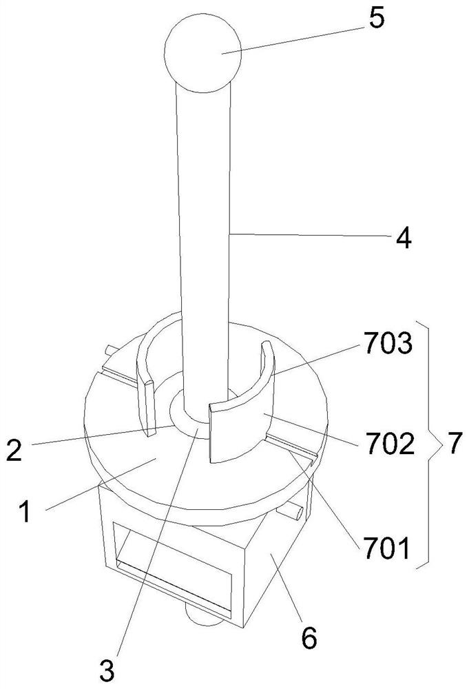
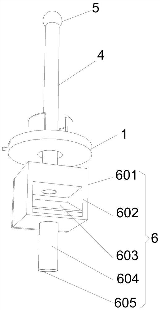
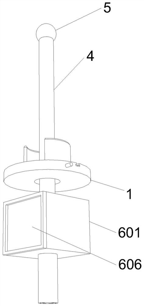
[0035] Embodiment: a kind of penetrating cavity detection equipment, such as Figure 1-Figure 9 As shown, it includes a fixed plate 1, the fixed plate 1 is a circular plate, the middle position of the fixed plate 1 is provided with a middle hole 2, the middle hole 2 is a circular through hole, and the middle position of the middle hole 2 is fixedly installed with a middle sleeve 3. The middle sleeve 3 is a circular sleeve. The upper end of the fixed plate 1 is vertically provided with an extension rod 4. The extension rod 4 is a cylindrical hollow tube and the extension rod 4 extends to the bottom of the fixed plate 1 through the hole in the middle of the middle sleeve 3. The upper end of extension rod 4 is fixedly equipped with ball cover 5, and ball cover 5 is a transparent spherical shell, and extension rod 4 is provided with hand-held mechanism 6 on one side of fixed plate 1 lower end.

[0036]Hand-held mechanism 6 comprises equipment box 601, observation slot 602 and refl...


PUM


Abstract

The invention relates to the technical field of medical treatment, and discloses probing type cavity detection equipment. The equipment comprises a fixing plate; the fixing plate is a circular plate;a middle hole is formed in the middle of the fixing plate; the middle hole is a circular through hole; a middle sleeve is fixedly installed in the middle of the middle hole; an extension rod is vertically arranged at the upper end of the fixing plate; the extension rod is a cylindrical hollow tube and extends to the position below the fixing plate through a hole in the middle of the middle sleeve;a ball cover is fixedly installed at the upper end of the extension rod; and a handheld mechanism is arranged on the side, at the lower end of the fixing plate, of the extension rod. According to theinvention, an arc-shaped plate is arranged to be in an arc shape, and a port of a cavity can be expanded and squeezed outwards through the arc shape of the arc-shaped plate, so that the whole equipment can be fixed at the port of the cavity, it is ensured that the equipment is fixed at the port of the cavity in a detection process of the whole equipment, the stability during detection is ensured,and the whole detection result is prevented from being influenced by vibration or displacement of the whole equipment in the detection process.

Description

technical field [0001] The invention relates to the field of medical technology, in particular to a penetrating cavity detection device. Background technique [0002] Endoscopy is a kind of optical instrument inspection that is sent into the body through the natural cavity of the human body from the outside to check the diseases in the body. [0003] At present, when the penetrating cavity detection equipment on the market is used, the image inside the cavity is usually collected through the connection of the camera, and the camera cannot be accurately changed after the camera is extended to the inside of the cavity through the device. Angle and shooting range, thus affecting the detection quality of the entire device. To this end, we propose a penetrating cavity detection device. Contents of the invention [0004] The present invention mainly solves the technical problems existing in the above-mentioned prior art, and provides a penetrating cavity detection device. [...

Claims


Application Information

Patent Timeline
Patent Type & Authority Applications(China)
IPC IPC(8): A61B1/04A61B1/045A61B1/32
CPCA61B1/00064A61B1/00066A61B1/04A61B1/045A61B1/32
Inventor 佘娜谢建锋赵小东邓文军
Owner 惠州市小鹅医疗科技有限公司
Why Eureka
Try Eureka