Anti-falling device for clinical nursing
A technology of anti-fall device and driving device, which is applied in transportation and packaging, vehicle rescue, medical science, etc., can solve the problems of patient falling, patient physical injury, and no patient setting.
- Summary
- Abstract
- Description
- Claims
- Application Information
AI Technical Summary
Problems solved by technology
Method used
Image
Examples
Embodiment 1
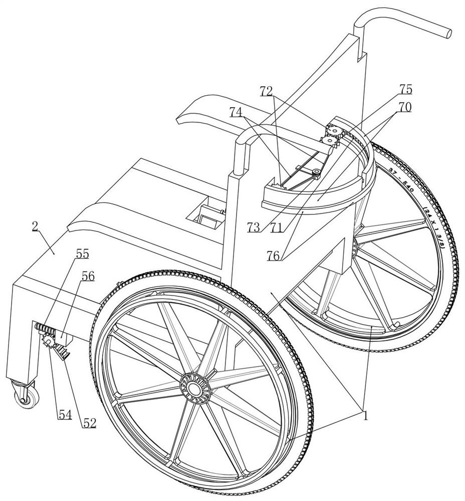
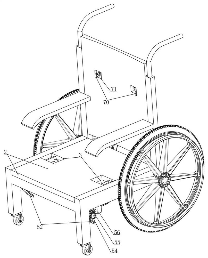
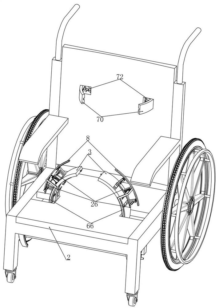
[0045] Embodiment 1, this embodiment provides a clinical nursing anti-drop device, refer to the attached figure 1 As shown, it includes a walking chair 1, which is characterized in that we rotate and install a bearing plate 2 on the walking chair 1 (that is, the cushion of the walking chair 1, so that the patient sits on the walking chair 1), refer to the attached image 3 As shown, we have two arc-shaped frames 3 horizontally spaced on the carrying plate 2, and the two arc-shaped frames 3 are horizontally rotated and mounted on the carrying plate 2 along one end of the arc extension direction and connected to the supporting plate 2. The active drive device on the end face, initially, when the device is not in use, the two arc-shaped frames 3 are placed on the lower end face of the bearing plate 2, as attached figure 2 As shown in , if the patient needs to sit in a wheelchair and transfer on a relatively flat road surface (for example, indoors), there is no need to move the t...
Embodiment 2
[0052] Embodiment 2, on the basis of embodiment 1, with reference to appended Figure 8 As shown, we are provided with a rectangular tube 11 that is installed in a sliding fit with the clamping plate 6 on the moving arc plate 4, referring to the attached Figure 15 As shown, the indirect transmission device includes a first gear 12 that is rotatably installed in the rectangular cylinder 11 and the first gear 12 meshes with a first rack 13 that is vertically slidably installed in the rectangular cylinder 11. The drive spring 7 is connected to the first Between a tooth bar 13 and the clamping plate 6 (we set it as a rectangle when setting the first tooth bar 13 and set its bottom as an opening, we are provided with two driving springs 7, as attached Figure 15 shown), when the arc-shaped rack 8 rotates under the drive of the driven drive device, the arc-shaped rack 8 drives the second gear 15 meshed with it to rotate (the second gear 15 is mounted on the arc-shaped frame 3 in ro...
Embodiment 3
[0055] Embodiment 3, on the basis of embodiment 2, with reference to appended Figure 15 As shown, the clamping plate 6 includes a connecting rod 16 vertically slidably installed in the rectangular tube 11, and we fixedly install a friction arc plate 17 coaxial with the arc frame 3 at the lower end of the connecting rod 16, so The upper end of the driving spring 7 is connected to the first rack 13, and the lower end of the driving spring 7 is fixedly connected to the connecting rod 16. When we set the connecting rod 16, the thickness of the vertically sliding fit part with the rectangular cylinder 11 is smaller than that of the connecting rod 16. The thickness of the connection part between the lower end and the friction arc plate 17 is set in order to provide accommodation space for the first pulley set 14, the first gear 12, and the first rack 13 (because the space in the rectangular cylinder 11 is certain, we only have The upper end of the connecting rod 16 and the sliding ...
PUM
 Abstract
Description
Claims
Application Information
 - R&D
- Intellectual Property
- Life Sciences
- Materials
- Tech Scout
- Unparalleled Data Quality
- Higher Quality Content
- 60% Fewer Hallucinations
Browse by: Latest US Patents, China's latest patents, Technical Efficacy Thesaurus, Application Domain, Technology Topic, Popular Technical Reports.
© 2025 PatSnap. All rights reserved.Legal|Privacy policy|Modern Slavery Act Transparency Statement|Sitemap|About US| Contact US: help@patsnap.com


