
Cab active vibration reduction method and system and engineering vehicle

An active vibration reduction, cab technology, applied in vehicle seats, vehicle parts, special positions of vehicles, etc., can solve the problems of manual adjustment, uncomfortable vibration of construction vehicles, time-consuming and laborious, and achieve the effect of improving vibration comfort.

Pending Publication Date: 2020-12-25
JIANGSU XCMG CONSTR MASCH RES INST LTD
View PDF10 Cites 2 Cited by
  • Summary
  • Abstract
  • Description
  • Claims
  • Application Information

AI Technical Summary

Problems solved by technology

[0005] The existing technology has the following defects: the existing mechanical damping system can only provide basic damping, and the height needs to be adjusted manually, which is time-consuming and laborious. The existing airbag damping seat is limited to height adjustment, and there is no adjustable seat softness and hardness. function, it is impossible to adjust the softness and hardness of the seat according to the real-time vibration situation, and to carry out active control so as to adapt to different road conditions. Provides a more comfortable working environment for drivers who work for a long time
[0006] Although there is an active control damping system in the prior art, it only alleviates driver fatigue through vibrating components, and does not fundamentally solve the problem of uncomfortable vibration of engineering vehicles

Method used


Image

  • Cab active vibration reduction method and system and engineering vehicle
  • Cab active vibration reduction method and system and engineering vehicle
  • Cab active vibration reduction method and system and engineering vehicle

Examples


Embodiment 1

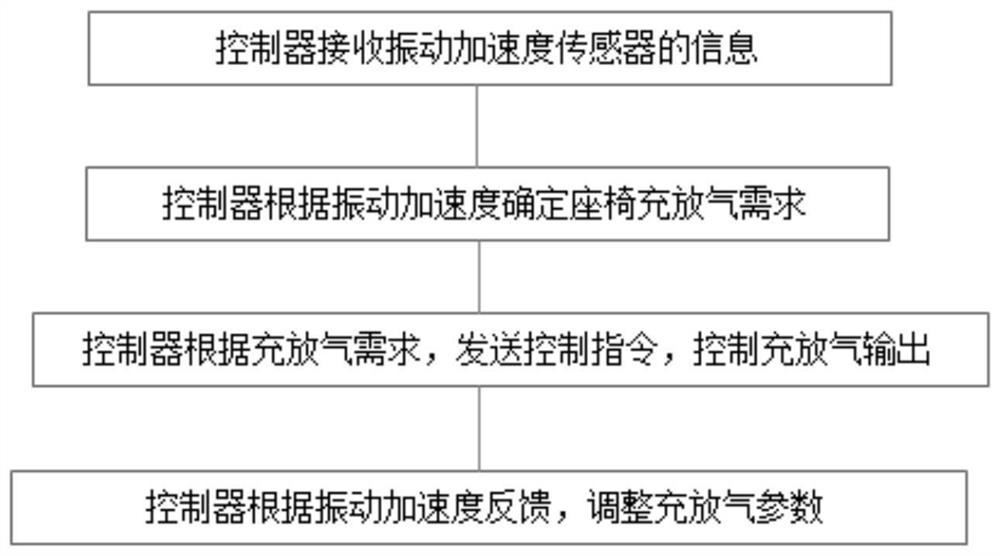
[0046]An active vibration reduction method for a cab, which controls the cushion and back airbag parameters of an active vibration reduction seat based on vibration acceleration information, including:

[0047]Acquire vibration acceleration information of the seat cushion and backrest, and the corresponding vibration acceleration setting range; the vibration acceleration information includes frequency peaks, through-frequency vibration, and order tracking;

[0048]Judge whether the vibration acceleration of the current cushion and backrest is within the set range;

[0049]In response to the vibration acceleration of the seat cushion and backrest not within the set range, a command is sent to control the opening of the proportional valve to inflate and deflate the cushion and backrest airbag structure until the vibration acceleration of the seat cushion and backrest is within the set range.

[0050]The active vibration damping method of the driver's cab further includes: obtaining pressure infor...

Embodiment 2

[0055]An active vibration damping device for a cab includes:

[0056]The information acquisition module is used to: acquire vibration acceleration information of the cushion and backrest, and the corresponding vibration acceleration setting range; the vibration acceleration information includes frequency peaks, through-frequency vibrations, and order tracking;

[0057]The judgment module is used to judge whether the vibration acceleration of the current cushion and backrest is within the set range;

[0058]Start the control module for: in response to the vibration acceleration of the cushion and backrest being out of the setting range, send a command to control the opening of the proportional valve, and inflate and deflate the cushion and backrest airbag structure until the vibration acceleration of the cushion and backrest is within the setting Within range

[0059]The pressure monitoring module obtains the pressure information of the cushion and backrest airbag during the inflation process; i...

Embodiment 3

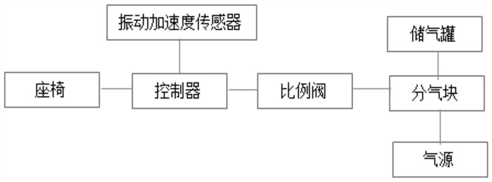
[0061]An active damping system for a cab includes a seat and the above-mentioned active damping device for the cab. The active damping device for the cab includes a memory and a processor. The memory is used to store instructions that are used to control the The processor operates to execute the aforementioned method for active damping of the cab.

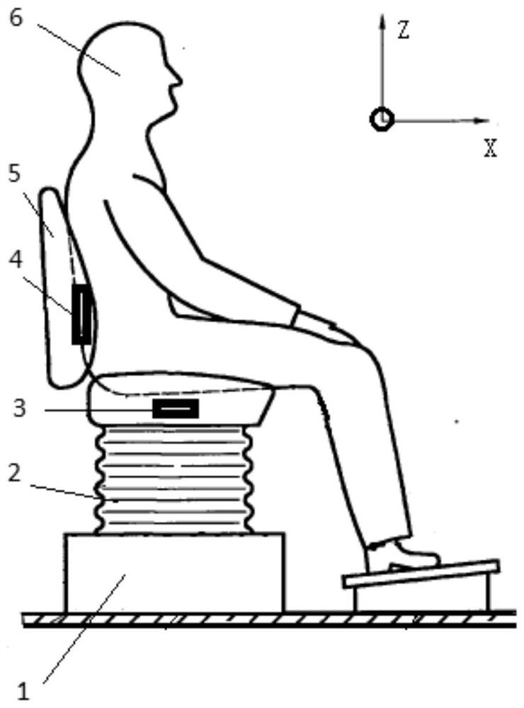
[0062]In some embodiments, the seat includes a seat base 1, a seat cushion 2 and a backrest 5. The seat base 1 is used to connect to the cab floor, and the seat cushion 2, the backrest 5 are installed on the seat base 1. The upper part is of airbag structure;

[0063]It also includes a cushion vibration acceleration sensor 3 and a backrest vibration acceleration sensor 4;

[0064]The cushion vibration acceleration sensor 3 is arranged on the inner surface of the cushion, and is used to monitor the vibration acceleration value of the cushion;

[0065]The backrest vibration acceleration sensor 4 is arranged on the inner surface of the backrest for mon...


PUM


Abstract

The invention discloses a cab active vibration reduction method and system and an engineering vehicle. The method comprises the steps that cushion and backrest vibration acceleration information and acorresponding vibration acceleration setting range are obtained, wherein the vibration acceleration information comprises a frequency peak value, pass frequency vibration and order tracking; whetherthe current cushion and backrest vibration acceleration is within the set range or not is judged; in response to the fact that the cushion and backrest vibration acceleration is not within the set range, an instruction is sent to control a proportional valve to be opened, and cushion and backrest air bag structures are inflated and deflated till the cushion and backrest vibration acceleration is adjusted to be within the set range; in the inflating process, pressure information of the cushion and the backrest air bags is obtained; in response to the fact that the pressure of the cushion and backrest air bags exceeds the corresponding upper limit values, an instruction is sent to control the proportional valve to be closed and stop inflating; in the inflating and deflating process, flow information of the cushion and the backrest air bags is obtained; and in response to the fact that the flow of the cushion and backrest air bags exceeds the corresponding limit values, an instruction issent to control reduction of the opening of the proportional valve.

Description

Technical field[0001]The invention belongs to the technical field of engineering machinery, and specifically relates to an active vibration reduction method and system for a cab and an engineering vehicle.Background technique[0002]At present, construction vehicles, including excavators, road rollers, skid steer loaders, graders, etc., are widely used in construction sites such as construction, roads, mines, ports, etc. The road surface and working environment of the work site are relatively harsh. Accompanied by huge instantaneous impact, low-frequency vibration and shaking are generated. As the group of construction machinery drivers continues to expand, their requirements for the working environment are also increasing, which places higher requirements on the vibration comfort of the cab.[0003]Due to the diversity and uncertainty of construction operations, the comfort of the cab will also change. During the long-term operation of the driver, the vibration that exceeds the limit w...

Claims


Application Information

Patent Timeline
Patent Type & Authority Applications(China)
IPC IPC(8): B60N2/52B60N2/50B60Q9/00
CPCB60N2/525B60N2/501B60N2/504B60Q9/00
Inventor 苏俊收王绍腾洪森
Owner JIANGSU XCMG CONSTR MASCH RES INST LTD
Learn More