Self-dewatering stable buoyancy tank

A stable, buoyant tank technology, applied to floating buildings, using auxiliary nozzles or propellers to reduce ship movement, etc., can solve the problems of low stability of buoyant tanks, achieve high safety, moderate impact, and ensure stability Effect

Active Publication Date: 2020-12-25
HUZHOU YUEBIN INTELLIGENT TECH CO LTD
View PDF9 Cites 1 Cited by
  • Summary
  • Abstract
  • Description
  • Claims
  • Application Information

AI Technical Summary

Problems solved by technology

[0005] The purpose of the present invention is to solve the problem of low stability of most traditional floating tanks in wind and waves, and to provide a self-draining stable floating tank that can effectively resist wind and waves

Method used


Image

  • Self-dewatering stable buoyancy tank
  • Self-dewatering stable buoyancy tank
  • Self-dewatering stable buoyancy tank

Examples


Embodiment 1

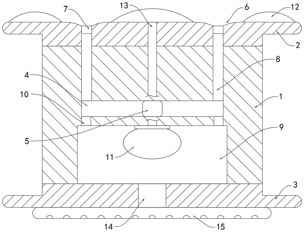
[0024] Such as Figure 1-2 Shown, a kind of self-removing water-type stable type buoyant tank comprises box body 1, and the upper and lower sidewalls of box body 1 are respectively fixedly connected with upper connection block 2 and lower connection block 3, above is the prior art, will not do it here Too much to repeat.

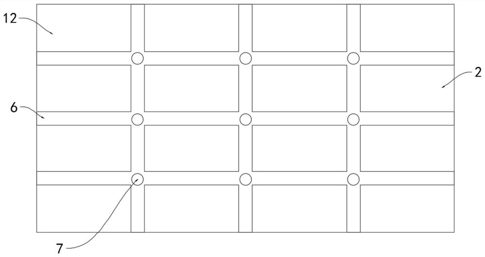
[0025] The interior of the box body 1 is provided with a sliding chamber 4 arranged horizontally, and the sliding block 5 is slidably connected to the sliding chamber 4. The upper side wall of the box body 1 is provided with a plurality of staggered water collection grooves 6, and the intersection of the plurality of water collection grooves 6 are equipped with drainage holes 7 (such as figure 2 shown), it is worth mentioning that the orifices of a plurality of drainage holes 7 are all lower than the bottom of the sump 6 (such as figure 1 Shown), the water in the sump 6 is accumulated to the orifice of the drain hole 7.

[0026] A plurality of drainage h...

Embodiment 2

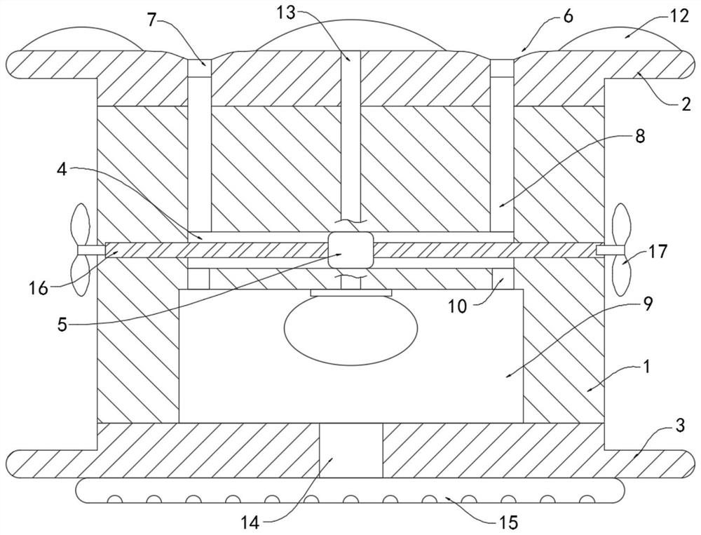
[0035] Such as image 3 As shown, the difference between this embodiment and Embodiment 1 is that the sliding chamber 4 is provided with a threaded rod 16 coaxially arranged with the sliding chamber 4, and the threaded rod 16 is arranged through the sliding block 5 and is connected with the screw thread on the outer wall. The sliding block 5 is threaded. It should be noted that the cross section of the sliding chamber 4 is rectangular, which can limit the sliding block 5, thereby driving the threaded rod 16 to rotate during the sliding process of the sliding block 5 .

[0036] Both ends of the threaded rod 16 extend to the inside of the casing 1 and are rotatably connected to the casing 1. Two push fans 17 are arranged outside the casing 1, and the rotating shaft of each push fan 17 extends to the inside of the casing 1 and is connected to the casing 1. It is fixedly connected with the end of the threaded rod 16 .

[0037] In this embodiment, when the wind and waves are relat...


PUM


Abstract

The invention belongs to the field of water appliances, and particularly relates to a self-dewatering stable buoyancy tank. The self-dewatering stable buoyancy tank comprises a tank body, an upper connecting block and a lower connecting block are fixedly connected with the upper side wall and the lower side wall of the tank body correspondingly, a horizontally-arranged sliding cavity is formed inthe tank body, and a sliding block is slidably connected into the sliding cavity; and a plurality of staggered water collecting grooves are formed in the upper side wall of the tank body, drain holesare formed in the intersections of the plurality of water collecting grooves, the plurality of drain holes communicate with the sliding cavity through one-way guide pipes arranged in the tank body, anair collecting cavity is formed in the lower end of the sliding cavity, the air collecting cavity communicates with the sliding cavity through one-way communicating pipes, and an elastic air bag is fixedly connected with the inner top surface of the air collecting cavity. According to the self-dewatering stable buoyancy tank, when gas in the air collecting cavity is sprayed out through a plurality of gas spraying holes in a gas spraying pipe, upward acting force borne by the whole buoyancy tank can more evenly act on the lower side wall of the lower connecting block, and therefore the whole buoyancy tank can be more stable in the gas spraying process.

Description

technical field [0001] The invention belongs to the field of water appliances, in particular to a self-water-removing stable floating tank. Background technique [0002] When carrying out water operations, it is often necessary to build temporary corridors on the water surface to facilitate the normal construction. At this time, it is necessary to use a large number of pontoons. The pontoon is a water device that is often used in seas or lakes. It is frequently used in work. [0003] During the use of the pontoon, usually multiple pontoons are bundled together to form a whole convenient passage on the water. Most of the traditional pontoons have a relatively simple structure. , the pontoons are prone to sway, which makes the stability of the entire water passage lower. Moreover, under the impact of wind and waves, sea water is easy to splash on the upper surface of the pontoons from the gaps between multiple pontoons, and people walk on the water passages. It is easy to sl...

Claims


Application Information

Patent Timeline
Patent Type & Authority Applications(China)
IPC IPC(8): B63B35/44B63B39/08
CPCB63B35/44B63B39/08
Inventor 沈超锋
Owner HUZHOU YUEBIN INTELLIGENT TECH CO LTD
Why Eureka
Try Eureka